Asian Spine J Search

CLOSE


Asian Spine J > Volume 13(6); 2019 > Article
Bhide, Srivastava, Purohit, Pinto, and Marathe: Computed Tomography Scan-Based Morphometric Analysis of Lateral Masses of Atlas Vertebrae in Normal Indian Population

Abstract

Study Design

A cross-sectional observational study involved the analysis of computed tomography (CT) scan data from 125 Indian subjects of 18 years or older with normal imaging findings. Scans were obtained from patients with head injuries as a part of the screening process along with brain CT scans.

Purpose

To establish the dimensions of lateral masses of the atlas vertebrae in normal disease-free Indian individuals.

Overview of Literature

Lateral mass fixation has become the standard of care in fixation of the supra-axial cervical spine. Many studies have investigated the dimensions of lateral masses in cadaveric specimens; however, studies involving the radiological morphometric analysis of the lateral masses of the atlas vertebra in living patients are lacking.

Methods

Subjects underwent craniovertebral junction CT scans during evaluations of head injury. All had normal radiology reports. The CT scans were obtained using a CT Philips Brilliance 64 machine (Philips, Amsterdam, Netherlands) with a slice thickness of 1 mm and then analyzed using Horos software ver. 2.0.2 (Horos Project, Annapolis, MD, USA) on a MacBook.

Results

Lateral masses of the atlas vertebrae were found to be larger in males than females and larger on the right than the left side. The angle of permissible medialization was found to be larger on the right side. The analysis of the average dimensions indicated the conventionally described screw positions to be safe.

Conclusions

The present study provides information that may help to establish standard dimensions of lateral masses of the atlas vertebrae among the normal Indian population. We demonstrate that there is no significant difference when compared with the Western population. The results presented here will be of use to clinicians as they may inform preoperative planning for lateral mass fixation surgeries.

Introduction

The craniovertebral junction comprises the basi-occiput, atlas, and axis vertebrae. Various pathologies that affect this region result in medullary compression and, ultimately, death. Such pathologies include congenital or acquired atlanto-axial dislocation, basilar invagination, traumatic fracture dislocations, and infective diseases, such as tuberculosis and tumors. Various methods of decompression and fixation have been described for the atlas and axis vertebrae. Of these, lateral mass fixation is the most commonly used technique. The trajectories and sizes of the screws have been described from cadaveric studies involving a limited number of specimens. The present study aimed to establish dimensions of lateral masses of the atlas vertebrae and the variation, if any, among the normal disease-free Indian population using a computed tomography (CT) scan analysis. The results of this study will provide guidance to clinicians and may inform preoperative planning.
This study includes a morphometric analysis of the lateral masses of the atlas vertebra in the normal Indian population.

Materials and Methods

This study was an observational cross-sectional study involving normal Indian subjects who attended a tertiary care hospital from 2013 to 2016. The sample size was 125 and included males and females aged 18 years or older. All subjects underwent craniovertebral junction CT scans as a part of the evaluation for a head injury. Only those with normal reports were included in the study. Exclusion criteria were cervical spine fracture/dislocation, rheumatoid arthritis, previous history of surgery, tumors, or cervical myelopathy with a spinal canal diameter of ≤12 mm. The evaluation of CT scans was carried out using Horos software ver. 2.0.2 (Horos Project, Annapolis, MD, USA) on a MacBook. The CT scans were recorded using a CT Philips Brilliance 64-slice machine (equipment no., 52952467; Philips, Amsterdam, Netherlands) with a slice thickness of 1 mm.
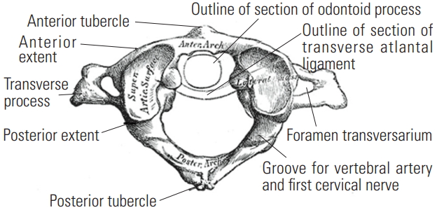
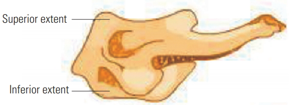
Various dimensions were analyzed, as described below. The extent of lateral masses of the atlas vertebra is illustrated in Figs. 1 and 2 [1].

1. Axial section

1) Standardization

Each section was taken parallel to the inferior articulating facets in the sagittal plane and centered on the vertical axis of the odontoid process in the coronal section.
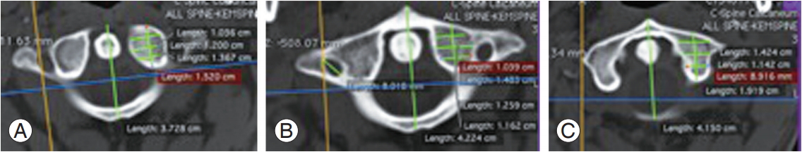
Three levels were evaluated as follows (Fig. 3A–C): (1) the level of inferior articulating facets, i.e., the inferior extent of lateral masses (Fig. 3A); (2) the level of the maximum diameter of the transverse foramen (Fig. 3B); and (3) the level of the superior articulating facets (Fig. 3C).
Lengths were measured at each level as follows. (1) The anteroposterior line was drawn in the central part extending from the anterior to the posterior extent. (2) The line was divided into four symmetric parts. (3) The lengths measured were as follows: anteroposterior distance (length); and medial-to-lateral distance (width) of the anterior, middle, and posterior parts.

2) Significance

The above measurements correspond to the screw parameters as follows. (1) The inferior facet relates to the inferior limit of the lateral masses. (2) The superior facet relates to the superior limit of the lateral masses.
The width of the posterior part of the lateral masses indicates the entry point of the lateral mass screw (according to the technique of Goel and Laheri [2], the center of the posterior end of the lateral masses is taken as the entry point). The width of the central part of the lateral masses indicates the center of the lateral mass screw. The maximum diameter of the transverse foramen is used to determine the narrowest width of the lateral masses. The width of the anterior part of the lateral masses is used to identify the exit point of the lateral mass screw.

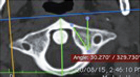
3) The angle of maximum medialization (at the level of the superior articulating facets) (Fig. 4)

The plane passing through the midpoint of the posterior wall of the lateral masses was identified by measuring the posterior height of the lateral masses on the sagittal view and dividing it in half, parallel to the inferior facet. The angle between the sagittal plane (a line parallel to the line passing between the anterior and posterior tubercles) and the line tangential to the medial wall, which passes through the midpoint of the posterior border.
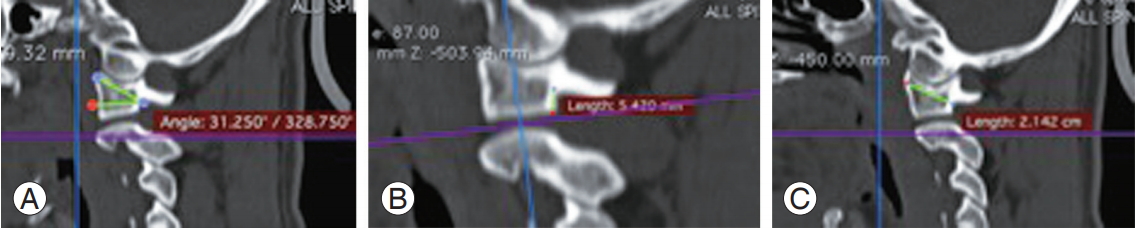
4) Significance

This is used to determine the maximum medial angulation of the screw to avoid touching the internal carotid artery (ICA) (the ICA usually lies in front of the middle or lateral thirds of the lateral masses of C1).

2. Sagittal section

1) Standardization

The plane passing through the midpoint of the posterior border of the lateral masses was confirmed on axial section, i.e., in the middle part of the lateral masses with the sagittal axis centered over the dens.
The parameters measured were as follows: (1) angle of cranialization, defined as the angle between the horizontal plane and the line joining a point 2.5 mm inferior to the posterior arch and anterior end of the superior surface of the lateral masses (Fig. 5A); (2) height of the lateral masses below the posterior arch (Fig. 5B); and (3) anteroposterior distance between the midpoint of the posterior wall of the lateral masses (determined by calculating the midpoint after measuring the posterior height) and a point on the anterior surface of the lateral masses, the line joining them making an angle of 15° to the horizontal (Fig. 5C).

2) Significance

This gives the approximate length of the lateral mass screw and the maximum angle of cranialization that can be used at the entry site to avoid entering the atlanto-occipital joint. And this gives the posterior part of the lateral masses below the posterior arch of the atlas represents the area that is accessed during surgery for the entry of the screw.
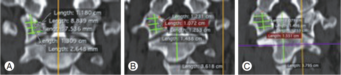
3. Coronal section

1) Standardization

The plane is parallel to the inferior facets on the sagittal section with a line joining the anterior and posterior tubercles parallel to the sagittal plane in the axial section. Three levels were evaluated as follows: (1) at the anterior end of the posterior arch (Fig. 6A); (2) maximum diameter of the transverse foramen (Fig. 6B); and (3) anteriormost extent of the lateral mass confirmed on the sagittal and axial sections (Fig. 6C).
At every level, a vertical line was drawn in the middle part, parallel to the line joining the apex of the dens and the midpoint of the inferior border of the body of axis; this line was divided into four symmetric parts. The lengths that were measured were: (1) mediolateral distance, i.e., the width of the superior, middle, and inferior parts; and (2) vertical distance in the middle, i.e., the height.

Results

The CT-scan-based analysis was carried out for the lateral masses of the left and right sides of the atlas vertebrae. The measured values are detailed in Tables 1 and 2. Statistical analysis revealed a significant difference between the male and female vertebrae (Table 3) and between the right and left sides (Table 4). Significant results are presented in Tables 14, with the following being most notable: (1) The widths of the lateral masses in the anteroinferior (p=0.01) and superoposterior parts (p=0.00) were smaller on the left side compared with the right. (2) The overall width of the lateral masses was smaller among the female than male subjects (p=0.00). (3) The maximum angle of medialization was larger on the right side than the left side (p=0.00). (4) The height of the lateral masses was larger on the right side and in male subjects; however, the difference was only marginally statistically significant (p=0.02).

Discussion

Treatments for fractures and dislocations of the cervical spine aim to protect the spinal cord from further damage, reduce malalignment, and provide long-term stability. Posterior stabilization of the cervical spine has been advocated mainly for fractures, disco-ligamentous diseases, post-laminectomy kyphosis, and instability due to various conditions, such as tumors, infections, and malformations.
The first technique of internal fixation was spinous process wiring; in 1942, Rogers [3] introduced his method of interspinous wiring. Modifications of this technique have since been reported to have good outcomes and few complications. With the progression of modern devices, screws and plates have been primarily used due to their superior anchorage, which allows a shorter fixation, appropriateness to functional recovery, and lighter immobilization device.
Atlanto-axial instrumentation is indicated for C1–C2 segmental instability resulting from trauma, such as transverse atlantal ligament rupture or dens fracture, rheumatoid arthritis, or congenital anomalies. Historically, the Gallie [4] technique has been used to stabilize C1–C2 as this posterior fusion technique ensures good resistance to flexion and is indicated in unstable extension conditions, such as transverse atlantal ligament rupture or dens fracture with anterior displacement. However, interspinous process wiring has limitations, particularly in patients with fractured facets, spinous process, or lamina with extension and rotational instability. In 1987, Magerl et al. [5] described a rigid C1–C2 transarticular screw fixation technique. These screws offer improved rigidity, especially in rotation, and increased maintenance of reduction than wired fusions. Magerl screws should be considered for patients with acute or chronic atlanto-axial instability, when revising C1–C2 pseudo-arthroses, as part of occipitocervical stabilization, or for patients who cannot tolerate halo immobilization. Irreducible fractures and aberrant vertebral artery anatomy are contraindications for transarticular screws.
The use of C1 lateral mass screws was first described by Goel and Laheri [2] in 1994 and later by Harms and Melcher [6] in 2001. However, the procedure is technically demanding; the most difficult aspect of inserting a screw into the C1 lateral mass is managing bleeding from the venous sinuses around the C1–C2 complex, which can increase blood loss and operative time considerably. These complications may even require the surgeon to abandon the lateral screw insertion as tremendous bleeding can obscure local landmarks. Resnick and Benzel [7] and Tan et al. [8] described a revised technique for C1 screw insertion in 2002 and 2003, respectively, involving the insertion of the screw through the C1 posterior arch (pedicle analog). The authors suggested that the new entry point will avoid the large venous sinuses; however, the revised technique places the vertebral artery at risk on the cephalad portion of the arch, which may result in C1 root irritation.
Currier et al. [9] described bicortical screw placement as violating the ICA at the anterior surface of the C1 lateral mass. The findings suggest that in approximately 65% of cases, the ICA is located in front of the C1 lateral mass. The ICA is in front of the lateral third of the lateral mass in over 50% of these cases; however, it is never located in front of the medial third.
Gupta and Goel [10] carried out a quantitative analysis of the anatomy of 50 dry atlas vertebrae to determine appropriate entry points and projection of C1 lateral mass screws. Lynch et al. [11] conducted a study on 120 dried atlas specimens and found that 98% could accommodate 3.5-mm screws at the mid portion of the lateral mass. In their series of 160 patients with atlanto-axial instability, Goel et al. [2] used 2.9-mm- and 2.7-mm-diameter screws in adults and pediatric patients, respectively, while applying the C1–C2 lateral mass screw fixation technique.
An anatomical and radiological study of C1 lateral mass screw fixation carried out at the Turkey University Faculty of Medicine found that the minimum height of the lateral mass is 13.66 mm posteriorly and 14.12 mm anteriorly [12]. As the only limitation for the diameter of screw is the anatomy of the entry zone below the posterior arch, larger-diameter screws can therefore be utilized for lateral masses with adequate bony structure. In this study, the maximum medial angulation for the screw was found to be 27.03° (on average) on the right and 32.63° on the left. In the case of medial trajectories of >30°, the screw penetrates into the spinal canal. Furthermore, when the cephalic trajectory is >28°, the screw enters the atlanto-occipital joint.
A cadaveric study of the vertebral artery to the C1–C2 vertebrae in an Indian population carried out by Cacciola et al. [13] revealed the thickness of the inferior facet under the posterior arch of the atlas to be 1.7–5.2 mm (average, 3.5 mm). The thickness of the posterior arch of the atlas separating the vertebral artery groove from the inferior facet was 2.2–4.8 mm (average, 3.8 mm). The vertebral artery foramen was in the transverse process lateral to the lateral mass of the C1 vertebra, and the groove for the vertebral artery on the superior surface of the posterior arch of the atlas was converted into a complete bony foramen in one of the 20 sides that were examined. The distance from the midline to the medial-most edge of the vertebral artery groove on the outer cortex of the posterior arch was 14.3–19.7 mm (average, 18.2 mm).
The present morphometric analysis of lateral masses of the atlas vertebrae in normal Indian individuals represents one of very few radiological studies carried out on living subjects. Most of the cadaveric studies also involved non-Indian subjects; therefore, the present study will help to establish normal morphometry in an Indian population, where individuals tend to have smaller builds compared with the Western population. This study will provide baseline data for any interventional procedures required to stabilize or decompress the atlas vertebrae.
Our results show that, in the normal Indian population, the lateral masses of the atlas are longer at the superior end, wider in the central area, and narrower anteroposteriorly. The maximum height is at the anterior, and the mean width of the lateral masses of the atlas at the maximum diameter level of the foramen transversarium was 11.3 mm on both sides (range, 8–15 mm on the left; range, 8.9–15 mm on the right). This finding implies that a 3.5-mm screw could be accommodated without violating the vertebral artery and maintaining a wide safety margin.
The height of the lateral masses below the posterior arch represents the area that is accessible for the screw entry. The mean posterior height of the lateral masses on the left side was 10.9 mm in the present study (range, 6.5–15 mm) and 11.98 mm (range, 9.5–17 mm) on the right side. The mean height below the posterior arch was 4.58 mm (range, 3.6–6.7 mm) on the left side and 4.42 mm (range, 2.8–6.4 mm) on the right side. This finding suggests that the posterior aspect of lateral mass can be easily entered using a burr.
The mean oblique length of the lateral masses from the sagittal section (which mimics the trajectory of a lateral mass screw) was 16.93 mm (range, 11.9–19.63 mm) on the left side and 15.82 mm (range, 11.3–17.9 mm) on the right. The variability of measurements indicates that screw length cannot be assumed but should be measured for each individual case on preoperative CT images or decided intraoperatively.
The maximum medial angulation of the medial wall of lateral masses was 29.8° (21.3°–33.4°) on the left side and 30.33° (21.9°–37°) on the right side. This result suggests that an angulation of 10°–15° toward the medial side can be used without violation of the spinal canal. The maximum cranial/sagittal angulation or angle of cranialization was 33.83° (range, 21°–48°) on the left side and 33.71° (range, 25°–45°) on the right side. This result suggests that a cranial angulation of 10°–15° is safe to use and will not violate the atlanto-occipital joint.

Conclusions

The morphometry of C1 lateral masses has been investigated in a number of cadaveric studies. These studies have produced extensive literature on the important dimensions of lateral masses with respect to screw insertion and have determined safe limits for screw size and the trajectory of insertion. The purpose of the present study was to determine these parameters in a normal Indian population. As can be seen from the observations mentioned in Table 5 [11,14-16], the dimensions of lateral masses of the atlas vertebrae do not significantly differ between the Indian and Western populations. However, a direct comparison is not possible as those involving Western populations were conducted on cadaveric dried specimens and were not radiological studies. Further studies on cadaveric specimens can be used to investigate Indian populations and confirm our findings.

Conflict of Interest

No potential conflict of interest relevant to this article was reported.

Notes

Author Contributions

PB: Methodology and data collection; SS: study design and concept; SP: study design and concept; DP: data analysis and statistics; and NM: review of literature and proof reading.

Fig. 1.
Atlas vertebra when viewed from above.
asj-2018-0227f1.jpg
Fig. 2.
Atlas vertebra when viewed from side.
asj-2018-0227f2.jpg
Fig. 3.
Axial section of atlas vertebra at the level of inferior articular process (A) at the level of maximum diameter of foramen transversarium (B) at the level of superior articular process (C).
asj-2018-0227f3.jpg
Fig. 4.
Angle of maximum medialization at the level of superior articular facets.
asj-2018-0227f4.jpg
Fig. 5.
Sagittal section of lateral mass of atlas showing angle of cranialization (A). Height of lateral mass below posterior arch (B). Antero-posterior distance (C).
asj-2018-0227f5.jpg
Fig. 6.
Coronal section at the level of anterior end of posterior arch (A). Maximum diameter of foramen transversarium (B). Anterior extent of lateral mass (C).
asj-2018-0227f6.jpg
Table 1.
Atlas lateral mass left side
Variable Mean±standard deviation Maximum Minimum
SAF length 18.41±1.7 22 15.7
LM middle part length 17.23±1.8 22 13.3
IAF length 15.90±1.63 19 11.4
SAF anterior width 10.70±1.3 13.5 8.5
LM middle part anterior width 10.90±2.0 15 8
IAF anterior width 9.63±1.4 12.3 6.7
SAF middle width 9.4±1 12.2 7.4
LM middle part middle width 11.3±1.5 15 8
IAF middle width 12.2±1.4 14.8 9.7
SAF posterior width 7.75±0.8 10 6.5
LM middle part posterior width 9.14±1.4 12 6.7
IAF posterior width 9.79±1.23 13.3 7.7
LM anterior part height 12.8±1.8 19 9.7
LM middle part height 11.4±1.9 17 9
LM posterior part height 10.9±2.2 15 6.5
LM height below posterior arch 4.58±0.75 6.7 3.6
LM screw approximate length on sagittal section 16.19±1.79 19.63 11.9
Maximum medialisation angle 29.02±2.8 33.4 21.3
Maximum cranialization angle 32.83±5.28 48 21

SAF, superior articulating facet; LM, lateral mass; IAF, inferior articulating facet.

Table 2.
Atlas lateral mass right side
Variable Mean±standard deviation Maximum Minimum
SAF length 18.20±2.16 22 15.7
LM middle part length 16.9±2 21 10.1
IAF length 15.55±1.8 20 12
SAF anterior width 10.8±1.01 12.3 8.8
LM middle part anterior width 11.34±2.0 16.3 8.2
IAF anterior width 10.1±1.45 14.1 7.9
SAF middle width 9.4±1.0 13 7.8
LM middle part middle width 11.3±1.4 15 8.9
IAF middle width 12.1±1.23 14 9.4
SAF posterior width 8.17±1.09 10.9 6.4
LM middle part posterior width 9.15±1.45 11.8 6
IAF posterior width 9.55±1.16 11.7 6.9
LM anterior part height 13.3±1.92 18.1 10.2
LM middle part height 11.98±1.9 17 9.5
LM posterior part height 11.1±2.6 17 6.5
LM height below posterior arch 4.42±0.8 6.4 2.8
LM screw approximate length on sagittal section 15.822±1.28 17.9 11.3
Medialization angle (°) 30.33±3.1 37 21.9
Cranialization angle (°) 33.71±4.76 45 25

SAF, superior articulating facet; LM, lateral mass; IAF, inferior articulating facet.

Table 3.
Comparison between dimensions of lateral mass of male and female subjects
Diameter Gender No. Mean±standard deviation p-value
(Axial) inferior articular facet anterior transverse distance M 88 0.996±0.137 0.14
F 37 0.966±0.162
(Axial) inferior articular surface middle transverse distance M 88 1.241±0.128 0.00
F 37 1.155±0.130
(Axial) inferior articular facet posterior transverse distance M 88 0.991±0.127 0.00
F 37 0.912±0.080
(Axial) inferior articular facet A-P distance in the middle M 88 1.586±0.173 0.14
F 37 1.550±0.178
(Axial) max diameter of transverse foramen anterior transverse distance M 88 1.120±0.196 0.57
F 37 1.104±0.241
(Axial) max diameter of transverse foramen middle transverse distance M 88 1.166±0.154 0.00
F 37 10.76±0.121
(Axial) max diameter of transverse foramen posterior transverse distance M 88 0.941±0.137 0.00
F 37 0.853±0.153
(Axial) max diameter of transverse foramen A-P distance in the middle M 88 1.695±0.227 0.09
F 37 1.743±0.138
(Axial) superior articular facet anterior transverse distance M 88 1.087±0.123 0.26
F 37 1.068±0.112
(Axial) superior articular facet middle transverse distance M 88 0.979±0.128 0.00
F 37 0.892±0.085
(Axial) superior articular facet posterior transverse distance M 88 0.822±0.090 0.00
F 37 0.736±0.102
(Axial) superior articular facet A-P distance in the middle part M 88 1.835±0.191 0.89
F 37 1.839±0.206
(Axial) at the level of condylar joint angle between sagittal plane and line joining posterior end of lateral mass and point 1 cm lateral to anterior tubercle M 88 29.500±3.282 0.14
F 37 30.117±2.358
(Coronal) at anterior end of posterior arch medial to lateral distance in the superior part M 88 0.773±0.157 0.00
F 37 0.622±0.132
(Coronal) at anterior end of posterior arch medial to lateral at middle part M 88 0.977±0.201 0.00
F 37 0.812±0.169
(Coronal) at anterior end of posterior arch medial to lateral distance in the inferior part M 88 0.856±0.187 0.00
F 37 0.727±0.162
(Coronal) at anterior end of posterior arch vertical distance in the middle part M 88 1.109±0.253 0.98
F 37 1.108±0.227
(Coronal) max diameter of transverse foramen medial to lateral superior part M 88 0.822±0.163 0.00
F 37 0.650±0.130
Coronal max diameter of transverse foramen medial to lateral distance in the middle part M 88 1.065±0.186 0.00
F 37 0.838±0.186
(Coronal) max diameter of transverse foramen medial to lateral distance in the inferior part M 88 0.980±0.256 0.00
F 37 0.726±0.165
(Coronal) max diameter of transverse foramen vertical distance in the middle M 88 1.200±0.187 0.00
F 37 1.113±0.198
(Coronal) anterior border of transverse foramen medial to lateral distance in the superior part M 88 0.919±0.155 0.69
F 37 0.911±0.133
(Coronal) anterior border of transverse foramen medial to lateral distance in the middle part M 88 1.205±0.203 0.49
F 37 1.225±0.200
(Coronal) anterior border of transverse foramen medial to lateral distance in the inferior part M 88 1.059±0.182 0.05
F 37 1.008±0.204
(Coronal) anterior border of transverse foramen vertical distance in the middle M 88 1.329±0.181 0.04
F 37 1.275±0.203
(Sagittal) AP distance between midpoint of posterior wall of lateral mass and a point on the anterior surface of lateral mass, the line joining which making and angle of 150 to the hori- zontal M 88 1.609±0.180 0.56
F 37 1.578±0.167
(Sagittal) height of lateral mass below posterior arch M 88 0.452±0.070 0.48
F 37 0.438±0.080
F 37 33.729±5.540
(Sagittal) angle between horizontal plane and line joining point 2.5 mm inferior to posterior arch and anterior end of superior surface of lateral mass (angle of cranialisation) M 88 32.195±3.396 0.03
F 37

M, male; F, female; AP, anterior-posterior.

Table 4.
Comparison between dimensions of lateral mass of right and left side
Diameter Side No. Mean±standard deviation p-value
(Axial) inferior articular facet anterior transverse distance R 125 1.011±0.145 0.01
L 125 0.964±0.142
(Axial) inferior articular surface middle transverse distance R 125 1.210±0.124 0.51
L 125 1.221±0.144
(Axial) inferior articular facet posterior transverse distance R 125 0.956±0.116 0.12
L 125 0.980±0.123
(Axial) inferior articular facet A-P distance in the middle R 125 1.560±0.185 0.14
L 125 1.592±0.163
(Axial) max diameter of transverse foramen anterior transverse distance R 125 1.135±0.209 0.15
L 125 1.096±0.210
(Axial) max diameter of transverse foramen middle transverse distance R 125 1.147±0.149 0.40
L 125 1.131±0.152
(Axial) max diameter of transverse foramen posterior transverse distance R 125 0.915±0.145 0.99
L 125 0.915±0.150
(Axial) max diameter of transverse foramen A-P distance in the middle R 125 1.693±0.209 0.23
L 125 1.724±0.202
(Axial) superior articular facet anterior transverse distance R 125 1.088±0.102 0.39
L 125 1.075±0.135
(Axial) superior articular facet middle transverse distance R 125 0.963±0.135 0.21
L 125 0.943±0.110
(Axial) superior articular facet posterior transverse distance R 125 0.817±0.109 0.00
L 125 0.776±0.087
(Axial) superior articular facet A-P distance in the middle part R 125 1.826±0.217 0.40
L 124 1.847±0.171
(Axial) at the level of condylar joint angle between sagittal plane and line joining posterior end of lateral mass and point 1 cm lateral to anterior tubercle R 125 30.337±3.151 0.00
L 125 29.029±2.801
(Coronal) at anterior end of posterior arch medial to lateral distance in the superior part R 125 0.719±0.156 0.40
L 125 0.737±0.173
(Coronal) at anterior end of posterior arch medial to lateral at middle part R 125 0.912±0.195 0.21
L 125 0.944±0.217
(Coronal) at anterior end of posterior arch medial to lateral distance in the inferior part R 125 0.819±0.189 0.91
L 125 0.816±0.190
(Coronal) at anterior end of posterior arch vertical distance in the middle part R 125 1.118±0.265 0.57
L 125 1.100±0.225
(Coronal) max diameter of transverse foramen medial to lateral superior part R 125 0.744±0.171 0.01
L 125 0.798±0.171
(Coronal) max diameter of transverse foramen medial to lateral distance in the middle part R 125 1.000±0.224 0.86
L 125 0.995±0.200
(Coronal) max diameter of transverse foramen medial to lateral distance in the inferior part R 125 0.940±0.279 0.03
L 125 0.869±0.235
(Coronal) max diameter of transverse foramen vertical distance in the middle R 125 1.198±0.194 0.04
L 125 1.149±0.192
(Coronal) anterior border of transverse foramen medial to lateral distance in the superior part R 125 0.894±0.160 0.01
L 125 0.940±0.133
(Coronal) anterior border of transverse foramen medial to lateral distance in the middle part R 125 1.214±0.208 0.79
L 125 1.208±0.195
(Coronal) anterior border of transverse foramen medial to lateral distance in the inferior part R 125 1.053±0.187 0.44
L 125 1.035±0.192
(Coronal) anterior border of transverse foramen vertical distance in the middle R 125 1.340±0.193 0.02
L 125 1.286±0.182
(Sagittal) A-P distance between midpoint of posterior wall of lateral mass and a point on the an- terior surface of lateral mass, the line joining which making and angle of 150 to the horizontal R 125 1.582±0.179 0.09
L 125 1.619±0.128
(Sagittal) height of lateral mass below posterior arch R 125 33.718±4.769 0.08
L 125 32.832±5.287
(Sagittal) angle between horizontal plane and line joining point 2.5 mm inferior to posterior arch and anterior end of superior surface of lateral mass (angle of cranialization) R 125 0.442±0.080 0.17
L 125 0.458±0.070

R, right; L, left; AP, anterior-posterior.

Table 5.
Comparison with other studies
Study Dimensions
SAF AP SAF width IAF AP IAF width LM width in the middle part LM AP in the middle part LM ph LM ah LM p width Height below arch Angle of cranialization Angle of medialization
Lynch et al. [11] (Switzerland) 19.73±1.71 16.93±1.61 8.68±1.55 4.19±1.06
Rocha et al. [14] 18.03 16.47 12.4 17.5 33.73 36.99
Wang et al. [15] (California) 15.6±2.4 17.2±2.1 7.3±1.3 19±5 33±4
Buteera et al. [16] (South Africa) 13.77±1.23 17.64±1.36 4.51±0.634
Present study 18.41±1.4 9.4±1 15.9±1.63 12.2±1.4 11.3±1.5 17.23±1.8 12.8±1.8 10.9±2.2 9.14±1.4 4.58±0.75 32.8±5.28 30.33±2.8

Values are presented as mean±standard deviation.

SAF, superior articulating facet; AP, anterior-posterior; IAF, inferior articulating facet; LM, lateral mass; ph, posterior part height; ah, anterior part height; p, posterior part.

References

1. Standring S, Borley NR, Garay H. Gray’s anatomy: the anatomical basis of clinical practice. 40th ed. Edinburgh: Churchill Livingstone/Elsevier; 2008.

2. Goel A, Laheri V. Plate and screw fixation for atlanto-axial subluxation. Acta Neurochir (Wien) 1994 129:47–53.
crossref pmid pdf
3. Omeis I, DeMattia JA, Hillard VH, Murali R, Das K. History of instrumentation for stabilization of the subaxial cervical spine. Neurosurg Focus 2004 16:E10.
crossref
4. Gallie WE. Fractures and dislocations of the cervical spine. Am J Surg 1939 46:495–9.
crossref
5. Magerl F, Grob D, Seeman P,Stable dorsal fusion of the cervical spine (C2-T1) using hook plates. Kehr P, Weidner A, editors. Cervical spine. New York (NY): Springer-Verlag; 1987. p.217–21.

6. Harms J, Melcher RP. Posterior C1-C2 fusion with polyaxial screw and rod fixation. Spine (Phila Pa 1976) 2001 26:2467–71.
crossref pmid
7. Resnick DK, Benzel EC. C1-C2 pedicle screw fixation with rigid cantilever beam construct: case report and technical note. Neurosurgery 2002 50:426–8.
crossref pmid
8. Tan M, Wang H, Wang Y, et al. Morphometric evaluation of screw fixation in atlas via posterior arch and lateral mass. Spine (Phila Pa 1976) 2003 28:888–95.
crossref pmid
9. Currier BL, Todd LT, Maus TP, Fisher DR, Yaszemski MJ. Anatomic relationship of the internal carotid artery to the C1 vertebra: a case report of cervical reconstruction for chordoma and pilot study to assess the risk of screw fixation of the atlas. Spine (Phila Pa 1976) 2003 28:E461–7.
crossref pmid
10. Gupta S, Goel A. Quantitative anatomy of the lateral masses of the atlas and axis vertebrae. Neurol India 2000 48:120–5.
pmid
11. Lynch J, Christensen D, Currier B. C1 lateral mass screws: technique and morphometric study. In: Proceedings of the American Association of Neurological Surgeons Meeting; 2001; Toronto, ON, Canada. Rolling Meadows (IL). American Association of Neurological Surgeons. 2001

12. Akay A, Ruksen M, Cagli MS, Kitis O, Erturk M, Zileli M. An anatomical and radiological study for C1 lateral mass screw fixation. J Neurol Sci 2013 30:328–36.

13. Cacciola F, Phalke U, Goel A. Vertebral artery in relationship to C1-C2 vertebrae: an anatomical study. Neurol India 2004 52:178–84.
pmid
14. Rocha R, Safavi-Abbasi S, Reis C, et al. Working area, safety zones, and angles of approach for posterior C-1 lateral mass screw placement: a quantitative anatomical and morphometric evaluation. J Neurosurg Spine 2007 6:247–54.
crossref pmid
15. Wang MY, Samudrala S. Cadaveric morphometric analysis for atlantal lateral mass screw placement. Neurosurgery 2004 54:1436–40.
crossref pmid pdf
16. Buteera A, Lukhele M. Anatomic study of the atlas for surgical planning of lateral mass screw fixation: is it safe in our population? SA Orthop J 2010 9:38–44.


ABOUT
ARTICLE CATEGORY

Browse all articles >

BROWSE ARTICLES
EDITORIAL POLICY
FOR CONTRIBUTORS
Editorial Office
Department of Orthopedic Surgery, Asan Medical Center, University of Ulsan College of Medicine
88, Olympic-ro 43-gil, Songpa-gu, Seoul 05505, Korea
Tel: +82-2-3010-3530    Fax: +82-2-3010-8555    E-mail: asianspinejournal@gmail.com                
Korean Society of Spine Surgery
27, Dongguk-ro, Ilsandong-gu, Goyang-si 10326, Korea
Tel: +82-31-966-3413    Fax: +82-2-831-3414    E-mail: office@spine.or.kr                

Copyright © 2024 by Korean Society of Spine Surgery.

Developed in M2PI

Close layer
prev next