


Introduction
The phenomenon of adjacent disc degeneration (ASD) following lumbar spine fusion has received considerable attention from spine surgeons. However, only a few studies have focused on the effects of “floating fusion” on the adjacent discs. For the purpose of clarity, we defined “floating fusion” as a fusion of native, unfused discs above and below the fusion segment. Classically, monosegmental floating fusion is performed for degenerative spondylolisthesis of L4 over L5 vertebra following degenerative disc disease of the L4–L5 disc. “Floating fusion” should be distinguished from the concept of “floating disc,” which was defined by Derincek et al. [1] as a “normal disc left alone between two surgically fused areas”. Thus, a floating L4–L5 disc refers to an unfused L4–L5 disc that lies between L3–L4 and L5–S1 fusion segments. The present study focuses on “floating fusion” and not on “floating discs.” We adopted the terminology recommended by Rousseau and Lazennec [2] who labeled the disc cranial to the floating fusion segment as the “suprajacent disc” and the disc caudal to the floating fusion as the “infrajacent disc”.
Brodsky et al. [3] published their experiences (spanning over three decades) with the floating fusion of the L4–L5 segment in a large cohort of 184 patients and reported poor outcomes in only 2% of them. Only 2.7% of the patients in their series had disc degeneration in the infrajacent disc (L5–S1) that required the extension of fusion to the sacrum. Their report challenged the pre-existing traditional belief that lower lumbar fusions, as a rule, should extend to include the lumbosacral segment. Ghiselli et al. [4] reported a similar experience with floating L4–L5 fusions more recently in which none of their 32 patients required the extension of fusion to the sacrum after a mean follow-up period of 7.3 years. Only one patient required decompression at the L5–S1 segment for radicular symptoms.
However, the reported outcomes of floating fusions in other studies appear to contradict the conclusions of the above studies. Bydon et al. [5], in a large cohort of 511 patients, compared the outcomes of floating lumbar fusions and fusions extending to the lumbosacral junction (performed over a period of 23 years) and concluded that floating fusions were significantly more likely to develop ASD than fusions extending to the lumbosacral junction. They found no significant difference in the ASD rates in the discs suprajacent to the fusion in both floating fusions and fusions extending to the sacrum. The ASD rates in the discs infrajacent to the fusion were significantly different between the two groups, with relatively high ASD rates in the floating fusion group. Miyakoshi et al. [6] evaluated the outcomes of posterior lumbar interbody floating fusions in 45 patients with over 5 years of follow-up and reported decreased height of both the suprajacent and infrajacent discs. No correlation was reported between imaging and clinical outcomes.
The present study aimed to employ finite element (FE) analysis to determine the magnitude of stress on the discs adjacent to a monosegmental, instrumented, and noninstrumented floating lumbar fusion of the L4–L5 spinal segment.
Materials and Methods
The steps followed for developing the FE models of the spine, including the baseline model and the models incorporating surgical interventions, are shown in the flow chart in Fig. 1.
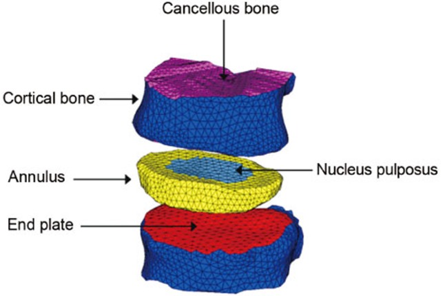
The FE modeling of the truncated vertebral unit (TVU): using the image processing software MIMICS, a 3D geometric model of the lumbar spine was generated from the computed tomography (CT) scan images of an adult male human subject. An FE model of the TVU for analysis using the advanced explicit nonlinear FE analysis tool LS-DYNA was then developed to obtain the compressive force–displacement response under quasi-static and impact loading conditions. This FE model comprised 22,511 elements and is shown in Fig. 2 with the key parts highlighted. It should be noted that the outer cortical bone and the end plates were modeled with 3,516 shell elements, whereas the vertebral body and the intervertebral disc were modeled using 18,995 solid elements.
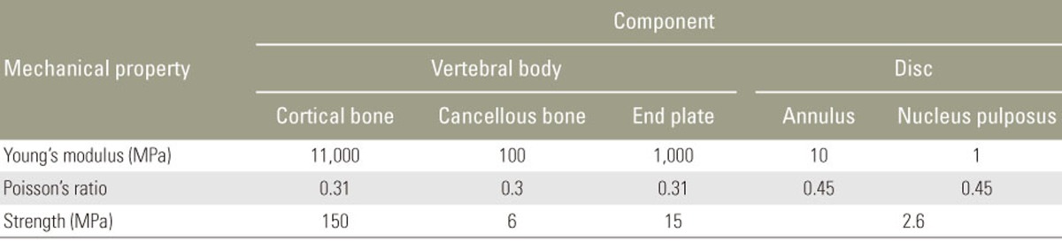
For the purpose of the present study, the mechanical behaviors of various tissues (Fig. 2) were represented with MAT 24 (piecewise linear plasticity models in LS-DYNA). Although bone is a composite material that exhibits orthotropy and inhomogeneity, modeling bone as an isotropic and homogenous material has a minimum effect on the accuracy of the results, with the most appropriate density–elasticity relationship of the bone tissue being specimen-specific. The properties of the material used are listed in Table 1. The values of the modulus and strength of cancellous bone and end plates presented in Table 1 were obtained from tests performed in the present study, whereas the properties of other tissues, i.e., the cortical bone and disc, were estimated based on the data reported in the literature [78]. The interface identified using the keyword Contact_Automatic_General in LS-DYNA was activated to capture contacts between various parts of the TVU model.
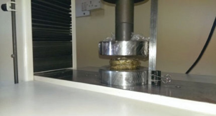
Experimental testing: in the present study, experimental investigation into the load–displacement responses of a human lumbar TVU under quasi-static loading conditions was performed. TVU samples obtained from the lumbar spinal column of an adult human male cadaver were subjected to quasi-static compressive tests in a UTM. The experimental characterizations of the elasto-plastic behavior of the L1-L2 TVU and L2-L3 TVU under quasi-static axial compressive loading were performed. The TVU under axial compression is shown in Fig. 3.
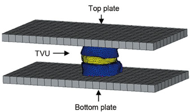
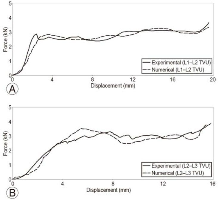
Quasi-static simulation: in the simulation of the UTM-based quasi-static compression test (Fig. 4), the top plate was provided a small steady downward velocity, and analysis was performed for a sufficiently long time. The variation in the resultant force generated between the top plate and the TVU (Fig. 4) with respect to the corresponding vertical displacement of the plate is compared with the experimental force–displacement curve, as shown in Fig. 5. Fig. 5 shows that the computed force-displacement curve is in good agreement with the test-based behavior. Thus, the FE modeling procedure adopted for the analysis of the TVU could be applied with confidence in simulation-driven studies.
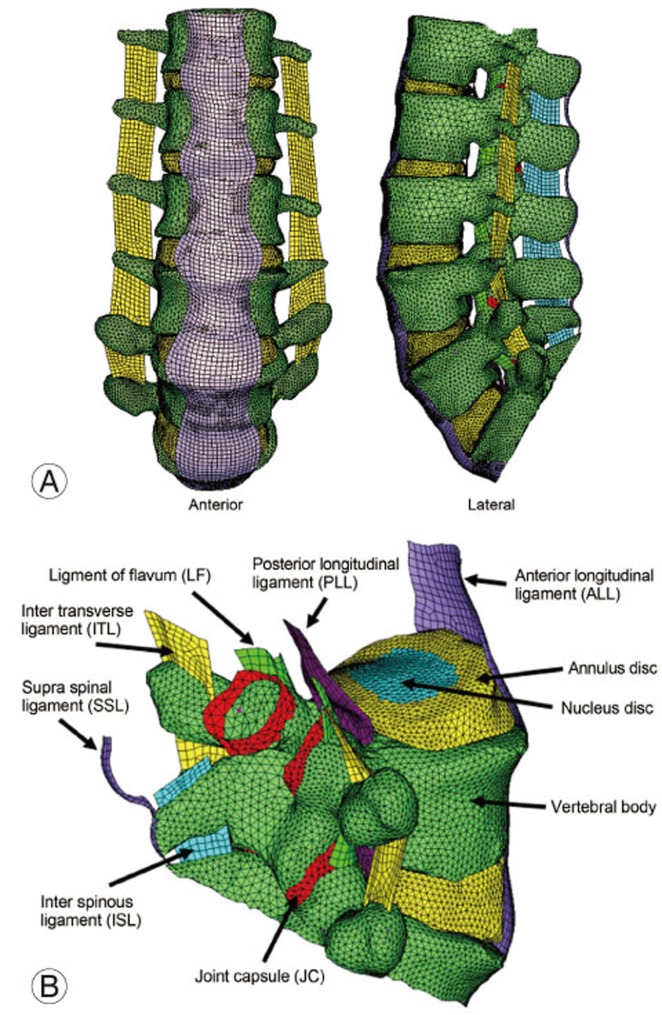
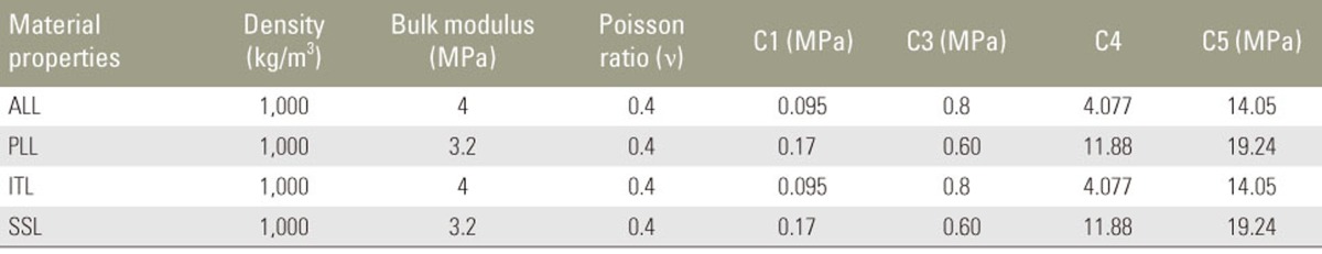
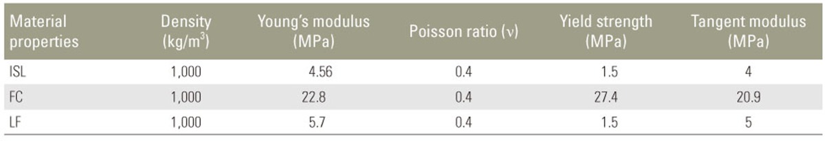
Development of the FE model of the intact lumbar spine: the FE model of the lumbar spine was developed from the relevant CT scan images using MIMICS. Fig. 6A shows the anterior and lateral views of the model, and Fig. 6B shows the detailed nomenclature for bony and soft tissue elements. The properties of the soft tissues and bony vertebral elements were obtained from the literature [910111213]. The soft tissues were modeled using MAT 91 (transversely isotropic hyperelastic model), representing an isotropic Mooney-Rivlin matrix with fiber reinforcement and strain energy characteristics similar to the qualitative material behavior of collagen. The material properties of the various soft tissues used in the present model are shown in Tables 2 and 3.
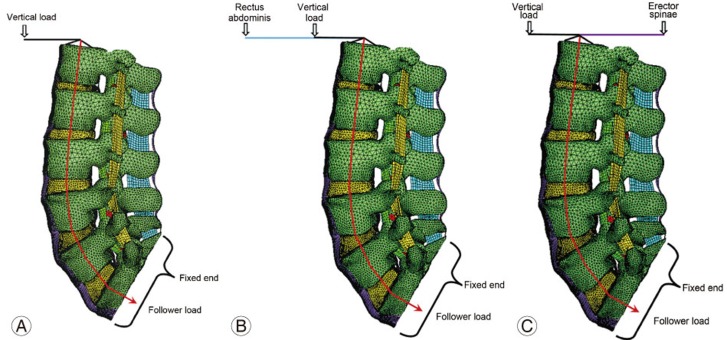
The intervertebral discs were modeled using higher order tetrahedral elements with an average element edge length of 1.5 mm. The ligaments and cortical bone were modeled using shell elements. The intact (no-fusion) lumbar spine model (L1–S1) shown in Fig. 6A was used as the baseline model. The loads and boundary conditions applied are shown in Fig. 7. A load of 350 N magnitude representing the upper body weight was applied 200 mm cranial and 30 mm ventral to the T12-L1 disc center, and a compressive follower load of 500 N was applied to simulate the effect of the local muscles. These loads were consistent with those used in the study by Calisse et al. [7] and Rohlmann et al. [14]. For flexion, a load of 50 N was applied at the rectus abdominis muscle location, with a vertical upper body load of 260 N and a follower load of 200 N. For extension, a load of 500 N was applied at the erector spinae muscle location, with a vertical upper body load of 260 N and a follower load of 200 N.
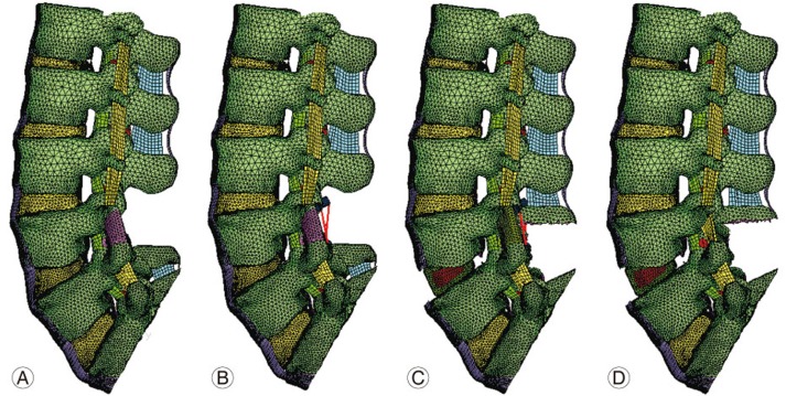
Development of the FE models of the lumbar spine with floating fusions: using the calibrated intact spine FE model, various other models were developed to mimic variations in floating fusion. These included posterior fusion without instrumentation, posterior fusion with pedicle screw instrumentation, posterior lumbar interbody fusion (PLIF) with instrumentation (stand-alone cages), and combined anterior and posterior (360°) fusion with instrumentation. Fig. 8A shows the lumbar spine FE models representing L4–L5 posterior floating fusion without instrumentation. In this model, a posterolateral bone graft was added to fuse the segment, and decompression was performed by removing the corresponding spinous processes, laminae, medial half of the facet joints, supraspinous ligament, interspinous ligament, intertransverse ligament, ligamentum flavum, and part of the facet capsule. Fig. 8B shows the FE model representing the posterior spinal decompression and fusion with pedicle screw instrumentation. Fig. 8C shows the FE model representing decompression and floating fusion using PLIF with cages. In these models, interbody bone cages with grafts were added to fuse the relevant segments. Fig. 8D shows a circumferential floating fusion model (combined anterior and posterior or 360° fusion) at the L4–L5 level. In this model, posterior decompression and pedicle screw instrumentation were combined with anterior instrumentation using a cage with bone grafts. The boundary and loading conditions for the models with fusion were the same as the conditions used for the intact spine model.
Results
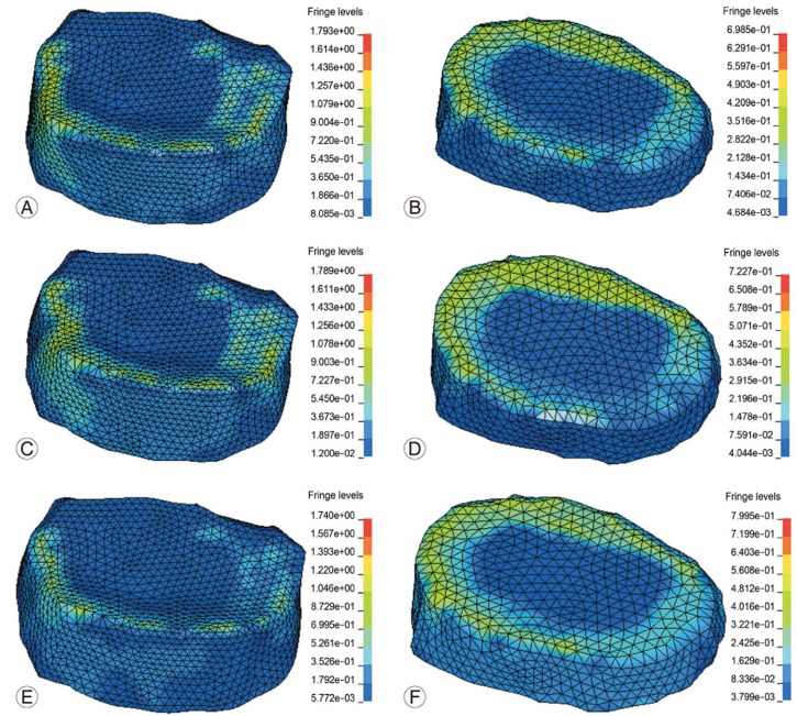
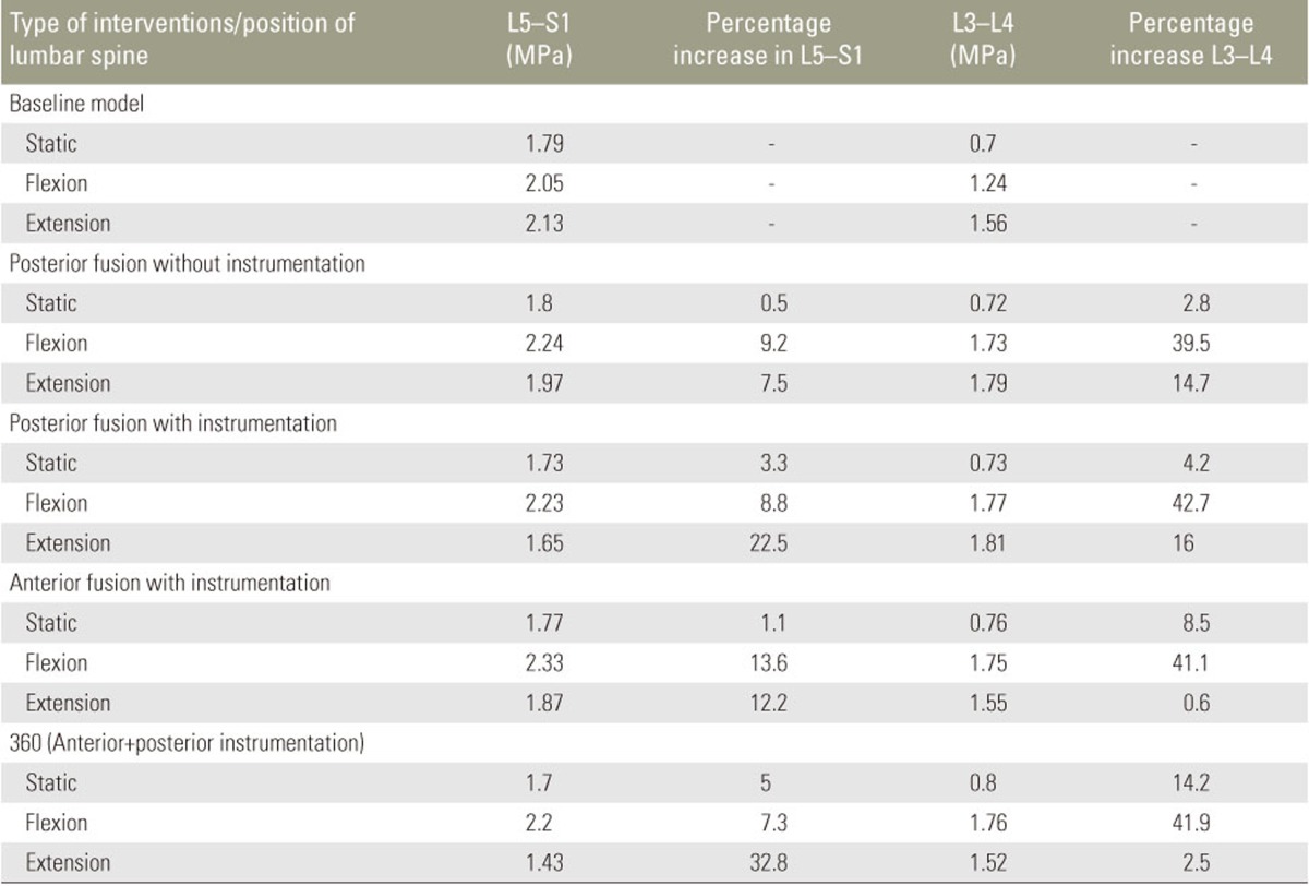
Stress distributions in the discs suprajacent and infrajacent to the L4–L5 disc were obtained for different types of interventions under static, flexion, and extension loading conditions. The location of the increased stress in the suprajacent and infrajacent discs was in the annulus fibrosus zone of the disc. The magnitudes of stress at the adjacent levels during different types of interventions at different levels of fusion were compared with those in the baseline no-fusion model. Table 4 shows the absolute values of the stress and the percentage increase over the baseline model. Stress plots for the maximum Von Mises stress are shown in Fig. 9.
Posterolateral noninstrumented fusion: the stress on the infrajacent disc (L5–S1) increased by 0.5%, 9.5%, and 7.2% under static, flexion, and extension loading conditions, respectively, and that on the suprajacent disc (L3–L4) increased by 2.8%, 39.8%, and 14.7% under static, flexion, and extension loading conditions, respectively.
PLIF with instrumentation (cages): the stress on the infrajacent disc (L5–S1) increased by 1.1%, 13.6%, and 12.2% under static, flexion, and extension loading conditions, respectively, and that on the suprajacent disc (L3–L4) increased by 8.5%, 41.1%, and 0.6% under static, flexion, and extension loading conditions, respectively.
Posterolateral instrumented fusion with pedicle screws: the stress on the infrajacent disc (L5–S1) increased by 3.3%, 8.8%, and 22.5% under static, flexion, and extension loading conditions, respectively, and that on the suprajacent disc (L3–L4) increased by 4.2%, 42.7%, and 16% under static, flexion, and extension loading conditions, respectively.
Combined anterior and posterior fusion with instrumentation (360° fusion): the stress on the infrajacent disc (L5–S1) increased by 5%, 7.3%, and 32.8% under static, flexion, and extension loading conditions, respectively, and that on the suprajacent disc (L3–L4) increased by 14.2%, 41.9%, and 2.5% under static, flexion, and extension loading conditions, respectively.
Discussion
Although ASD has been extensively studied, to date, ASD in floating lumbar fusions has been the subject of few studies. Disch et al. [15] reported a higher incidence of adjacent segment degeneration following floating L4–L5 fusions than that following L5–S1 and L4–S1 fusions over a mean follow-up period of 14 years. There seems to be a consensus that the adjacent disc cranial to the floating fusion (suprajacent disc) exhibits a high incidence of ASD (5%–70% incidence) following lumbar spine floating fusions. However, there is a lack of consensus regarding the extent of the effects of floating fusion on the disc infrajacent to the floating fusion (infrajacent disc). To date, the studies on long-term and medium-term clinical and imaging outcome have reported contradictory conclusions on the effects of floating fusion on the adjacent discs, especially the infrajacent disc. It is essential to clarify the effects of floating fusion on the infrajacent disc because the information will enable the surgeon to determine whether to limit the fusion to L5 and extend it to the sacrum.
In addition to ASD, postoperative radiculopathy due to infrajacent disc degeneration following floating fusions has also been the focus of few studies. Bydon et al. [5] reported a high incidence of ASD in the infrajacent disc following floating fusion but found a significantly low incidence of postoperative radiculopathy in these patients. Fusions to the sacrum are reportedly associated with a high incidence of reoperations for postoperative radiculopathy. Inoue et al. [16] and Miyakoshi et al. [6] have reported a significantly high incidence of decrease in the L5-S1 disc height following floating fusions at the L4–L5 level, which was not associated with significant clinical abnormalities in their studies. They attributed the decrease in the infrajacent disc height to increased stress in the disc after the floating fusion of the upper disc. Mesfin and Lemma [17] reported a bilateral pars fracture of L5 following the floating fusion of the L4–L5 disc in a patient with rheumatoid arthritis. These reports suggest that floating fusion causes ASD in the infrajacent disc, which does not correlate significantly with the symptoms of radiculopathy. However, in a recent study by Orita et al. [18], a 6.4% incidence of postoperative L5 radiculopathy was observed following floating fusion. The authors reported that multilevel floating fusions, male sex, and preoperative imaging abnormalities in the L5–S1 disc are associated with a high likelihood of postoperative radiculopathy and recommended fusion to the sacrum in the presence of preoperative abnormalities, such as coronal plane wedging and foraminal narrowing, in the L5–S1 disc.
In the present study, we compared the stress in the discs in the baseline no-fusion FE model with that in the fusion models. The important observation in our study was that stress increased in both the suprajacent and infrajacent discs following floating L4–L5 fusion. The increase in stress was between 0.5% and 5% in the infrajacent disc (L5–S1) and between 2.8% and 14.5% in the suprajacent disc (L3–L4) under static loading conditions. The stress was much higher following fusion in the flexion and extension loading conditions than in the static loading conditions. During flexion, the stress increased by 8.8%–13.6% in the infrajacent disc and by 39.5%–42.7% in the suprajacent disc. During extension, the stress increased by 7.5%–2.8% in the infrajacent disc and by 0.6%–16% in the suprajacent disc. Thus, the stress on the suprajacent disc is high in magnitude, but the infrajacent disc also experienced increased stress following floating fusion. Our findings are similar to those reported by Shin et al. [19] who stated increased stress in both the superior and inferior discs adjacent to the fusion segment. Their study involved a comparison between dynamic fusion and conventional instrumented fusion for lumbar spinal stabilization. Our study was focused on the effects of the subtypes (anterior, posterior, and combined) of fixed fusion on the adjacent discs. It is clear that all types of conventional instrumented floating fusions are associated with increased stress on the suprajacent and infrajacent discs. Chen et al. [8] also reported increased stress in both the suprajacent and infrajacent discs following floating anterior lumbar interbody fusion. Similar to the findings in our study, the stress in their study was higher in the suprajacent disc than in the infrajacent disc. Chen et al. [8] also reported higher levels of adjacent disc stress in longer (multisegmental) floating fusions and floating fusions involving lower lumbar segments than in upper lumbar segments.
Apart from pre-existing degenerative changes, other factors implicated in the degeneration of the disc infrajacent to a floating fusion include long fusion (polysegmental fusion) and rigidity of the fusion. Previous long-term studies on long segment thoracolumbar fusions for scoliosis that stopped short of the L4–L5 or L5–S1 segment reported a high incidence of degenerative changes in the unfused disc below the level of the fusion [2021].
In general, a higher incidence of ASD has been reported in instrumented fusions than in noninstrumented fusions. In their FE study, Jin et al. [22] assessed the effect of the rigidity of fusions, especially floating fusions. Increasing the rigidity of the fusion was associated with an increase in the stress in both suprajacent and infrajacent discs. However, the authors noted that the increased rigidity of instrumentation was associated with incremental stress on the suprajacent disc, whereas all types of instrumentation had similar effects on the infrajacent disc. In our study, the stress on the suprajacent disc increased with all types of instrumentation and was the highest following combined anterior and posterior fusion. The stress on the infrajacent disc also increased with instrumentation and varied according to the type of instrument (the lowest overall increase in stress following PLIF and the highest stress following 360° fusion).
Conclusions
It appears clear that both the suprajacent and infrajacent discs experience increased stress and exhibit changes in ASD over the long term, although the stress is higher on the disc suprajacent to the floating fusion than on the disc infrajacent to the fusion. Instrumentation (more rigid fusion) appears to increase the stress on both the suprajacent and infrajacent discs, but the magnitude of stress in higher on the suprajacent disc than on the infrajacent disc.