Asian Spine J Search

CLOSE


Asian Spine J > Volume 15(2); 2021 > Article
Bidari, Kamyab, Ghandhari, and Komeili: Efficacy of Computer-Aided Design and Manufacturing Versus Computer-Aided Design and Finite Element Modeling Technologies in Brace Management of Idiopathic Scoliosis: A Narrative Review

Abstract

The efficiency and design quality of scoliosis braces produced by the conventional casting method depends highly on the orthotist’s experience. Recently, advanced engineering techniques have been used with the aim of improving the quality of brace design and associated clinical outcomes. Numerically controlled machine tools have provided enormous opportunities for reducing the manufacturing time and saving material. However, the effectiveness of computer-aided brace manufacturing for scoliosis curve improvement is controversial. This narrative review is aimed at comparing the efficacy of braces made by the conventional method with those made by two computer-aided methods: computer-aided design and manufacturing (CAD-CAM), and computer-aided design and finite element modeling (CAD-FEM). The comparison was performed on scoliosis parameters in coronal, sagittal, and transverse planes. Scientific databases were searched, and 11 studies were selected for this review. Because of the diversity of study designs, it was not possible to decisively conclude which brace-manufacturing method is most effective. Similar effectiveness in curve correction was found in the coronal plane for braces made by using advanced manufacturing and conventional methods. In the sagittal plane, modern braces seem to be more effective than traditional braces, but there is an ongoing debate among clinicians, about which CAD-CAM and CAD-FEM brace provides a better treatment outcome. The relative effectiveness of modern and conventional methods in correcting deformities in the transverse plane is also a controversial subject. Overall, advanced engineering design and production methods can be proposed as time- and cost-efficient approaches for scoliosis management. However, there is insufficient evidence yet to conclude that CAD-CAM, and CAD-FEM methods provide significantly better clinical outcomes than those of conventional methods in the treatment of scoliosis curve. Moreover, for some factors, such as molding and the patient’s posture during the data acquisition, in brace curve-correction plan, the orthotist’s experience and scoliosis curve flexibility should be explored to confidently compare the outcomes of conventional, CAD-CAM, and CAD-FEM methods.

Introduction

Scoliosis is a three-dimensional (3D) musculoskeletal disorder associated with lateral deviation and axial rotation of the spine [1,2]. The Cobb angle, which represents spinal curvature, is the gold standard for assessing the severity of scoliosis [3]. The Cobb angle and other scoliosis parameters, such as axial rotation of the spine, trunk asymmetry, lordosis, and kyphosis, are measured by using either full-torso radiography, or noninvasive methods, such as surface topography [4,5]. Complications of scoliosis range from curve progression and back pain to cardiovascular disorders and psycho–social concerns [6-9]. In severe conditions, pulmonary complications and rarely death may occur [10]. According to epidemiological surveys, 2% to 3% of populations are affected by scoliosis [11-13], and the most common type is idiopathic (with an unknown etiology) [14].
Scoliosis treatment options are categorized into conservative and surgical approaches. Surgery is the preferred treatment for curves with a Cobb angle >45° [15]. Systematic reviews of conservative approaches, such as exercise therapy, electrical stimulation, and chiropractic treatments, have not found reliable evidence of effective outcomes [16-18]. However, orthotic management is the only proven method and the primary option for hindering curve progression in adolescent patients with curves from 20° to 45° [19,20]. A variety of orthotic designs have been developed, and their effect on the coronal curvature has been documented [18-21]. Examples are the Milwaukee brace (the oldest and most effective option, especially for high thoracic curves) [20,22,23], Cheneau [24], Lyonnaise [25], and Sforzesco [26]. The three main methods of brace designing and manufacturing are: conventional, computer-aided design with computer-aided manufacturing (CAD-CAM), and computer-aided design with finite element modeling (CAD-FEM). The details of each method are discussed in this review.

Evidence Acquisition

The Scopus, Web of Science, Ovid, PubMed, and Pedro databases were searched by using the following key words: “scoliosis”, “brace”, “spinal orthosis”, “computer-aided design”, “computer-aided manufacturing”, “CAD-CAM”, “brace fabrication”, “three-dimensional trunk acquisition”, “three-dimensional corrections”, “plaster mold”, “finite element method”, and “FEM”. The inclusion criteria included studies considering the efficacy of different methods of brace manufacturing published in English from 1990 to April 2019. Out of 25 publications found, 14 conference abstracts and duplicated studies (overlap >50%) were excluded, and only 11 journal publications were used in this review.

Conventional Methods

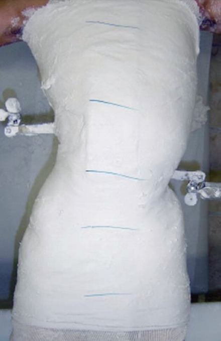
The conventional method of spine brace manufacturing includes molding a negative cast from the patient’s trunk and manually modifying the positive mold according to the spinal curve pattern [27,28] (Fig. 1). Therefore, the orthotist’s experience and expertise are key factors in treatment efficiency and comfort in the conventional method [29]. The conventional casting method has some drawbacks, such as a lengthy mold-rectifying process time, high volume of material consumption, low accuracy, not recording the patient’s body geometry data for future use, weak mechanical properties of the brace [30], low brace compliance because of point contact, high friction, pressure sores, and movement limitation. Moreover, the lack of aesthetic pleasure when using conventional braces is a concern, which may affect the social life of the patient [20,31-34].

CAD-CAM Methods

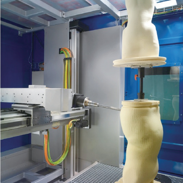
CAD-CAM methods have been used in brace designing and manufacturing with the aim of improving the quality of design and performance by eliminating drawbacks of the conventional casting method [29]. The first use of CAD-CAM systems in the industry was in the 1970s [35]. The first CAD-CAM system for prosthetics and orthotics was developed by Foort [36] and his research team at the University of British Columbia. The details of their system were presented to the International Society for Prosthetics and Orthotics World Congress in London in 1983 [30]. Since then, various CAD-CAM systems have been introduced in orthotics and prosthetics and have included Biosculptor, Orten, Rodin 4D, Tracer, and Vorum [37]. A CAD-CAM system consists of three units: a digitizer, a computer station, and a milling machine. The digitizer unit records 3D data of body shape in digital format, such as point cloud [30]. Digitizers are available in two types of fixed and portable technologies. Fixed type digitizers have a frame, which is equipped with cameras and light sources. The patient is placed in a frame and anatomical points on torso surface are marked, which will be used to rectify the mold, and the geometry of the external torso is scanned in <2 seconds [29]. Recently, portable digitizers have been developed with the aim of providing 3D geometry acquisition in different positions, such as bed resting, at the cost of longer acquisition times of 30 to 60 seconds [29]. The computer station (software) is used to convert the point cloud to a polygon mesh and design the brace mold considering the patient’s body profile. The milling machine carves a 3D model of the trunk [30] (Fig. 2). The use of CAD-CAM methods not only reduces manufacturing time to one third that of the conventional method but also helps standardize the manufacturing process and promotes accuracy. Wong et al. [37] analyzed the two methods (conventional/CAD-CAM) from the cast filling/ digitization process to completion of cast/image rectification and compared the time of brace manufacturing. “The results demonstrated that the mean rectification time of the CAD/CAM method was shorter than that of the conventional manual method by 108.3 minutes (63.5%)” [37]. Additionally, modern brace-manufacturing techniques help orthotists better educate and provide medical advice to patients in addition to achieving a higher hygiene level and less material consumption because of omitting the casting phase [28-30,37]. In the previous decade, the application of 3D printing, as a form of the CAD-CAM method, has expanded rapidly in clinical practice, such as in orthosis manufacturing [38-41]. The 3D printers leverage the use of new materials and complex designs of personalized orthoses that might be unfeasible or too costly to manufacture by using the computer numerical carving method [38,42-44].

CAD-FEM (Simulation Methods)

Simulation techniques, such as FEM, provide the possibility of evaluating the clinical effectiveness of brace treatments. The CAD-FEM methods apply FEM results as a feedback in the CAD-CAM process. The importance of simulation techniques is in measuring the torso–brace interaction, which is crucial information in the design of personalized braces. Simulation techniques consider the interaction of three main geometries: the skeleton, torso surface, and brace.
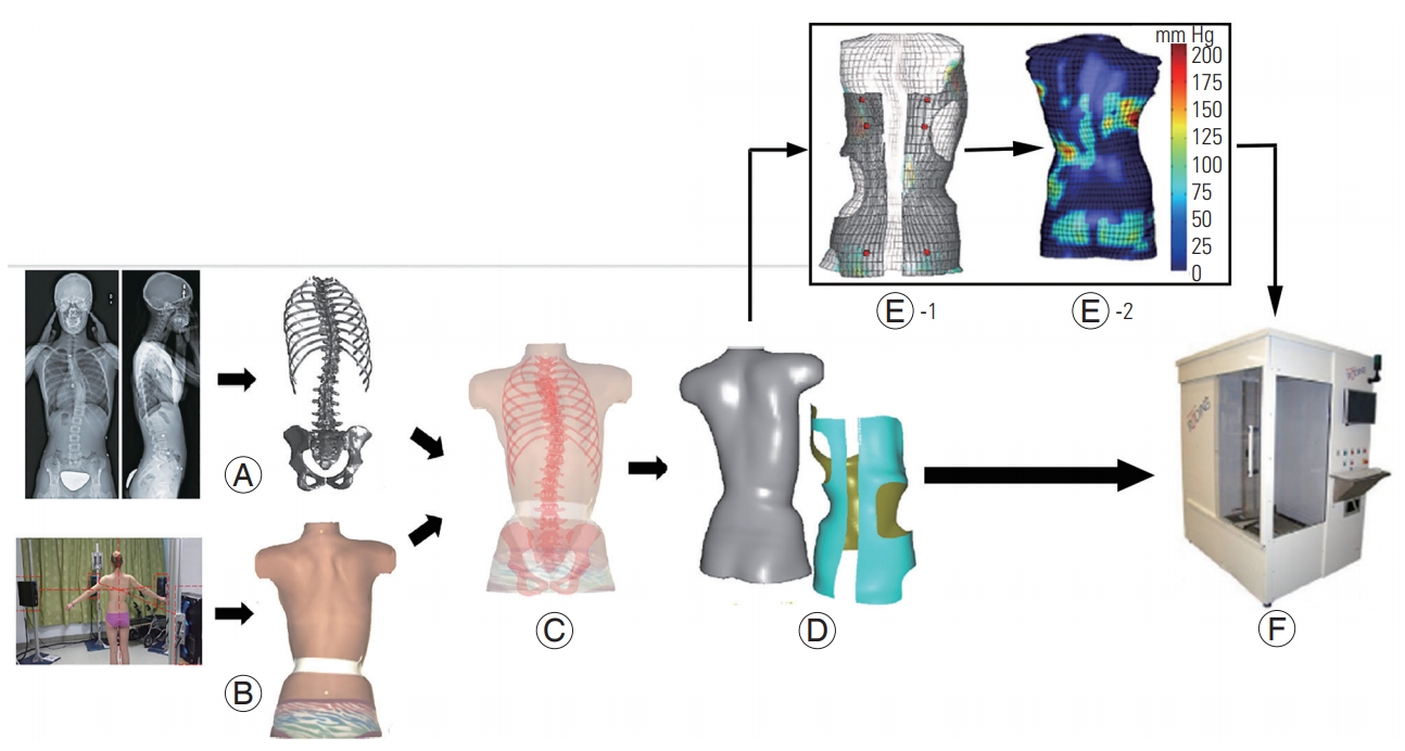
The skeletal geometry, including the thoracic and lumbar vertebrae, intervertebral disk, ribs, sternum, costal cartilage, and abdominal cavity, is obtained from biplane radiography (posterior, anterior and lateral views), which can be obtained by use of a low-dose radiographic imaging system, such as an EOS system (EOS Imaging, Paris, France) [45]. The external torso geometry is reconstructed by using a surface topography method from which the brace model is created by using CAD software. To prepare a personalized FEM, the skeleton and external torso models are registered by using radio-opaque markers that are a priori positioned on anatomical points of the patient’s torso. The assembly is meshed by applying a proper element type and size. The torso–brace interaction is simulated by contact properties defined between mating contact surfaces in FEM [46-50]. At the end of the simulation process, clinical indices, such as torso surface deformations and spinal curvature, are calculated, and brace geometric properties, such as brace trim line, opening area, strap numbers, and orientation are modified [46,51]. The process of modifying a brace model is iterated to improve the clinical indices. The optimized brace design that is speculated to result in the highest curve correction is selected and carved by a milling machine to be used as a base for thermoplastic shell thermoforming [46,51,52] (Fig. 3). The CAD-FEM braces intend to optimize the location and magnitude of pressure applied by brace pads to improve curve correction and decrease brace material (lighter and thinner brace) [46]. Furthermore, brace manufacturing using the CAD-FEM method has been shown to save about half of the time consumed in the conventional method [46]. When the results of finite element (FE) analysis are used in the design process, they reduce random decision-making and increase the effectiveness of the brace [53]. However, compared with the conventional method, advanced brace-manufacturing methods still rely to a lesser extent on the brace designer’s expertise, applied FE algorithm, brace quality, and pressure-pad characteristics. Table 1 summarizes the pros and cons of conventional, CAD-CAM, and CAD-FEM methods of brace designing and manufacturing.
The correlation between brace-manufacturing methods and scoliosis treatment outcomes is controversial. Some studies have reported approximately the same Cobb angle correction between conventional versus CAD-CAM [28,30,54] and between conventional versus CAD-FEM methods [46,51], whereas other studies have shown that the Cobb angle was better corrected by CAD-FEM methods than by CAD-CAM or conventional methods [53,55]. Despite the controversial results in comparing the efficiency of brace-manufacturing methods, to the best of our knowledge, no study has yet carefully reviewed the effect of these methods on scoliosis parameters, such as spinal curve in coronal, sagittal, and transverse planes, and the patient’s comfort. Hence, this review covers the effects of conventional, CAD-CAM, and CAD-FEM braces on key outcome measures of scoliosis, including the Cobb angle, sagittal profile, axial rotation of the vertebrae, and comfort.
Studies considering the efficacy of brace-manufacturing methods on clinical outcomes of scoliosis can be divided into four groups: group 1 studies investigated the efficacy of CAD-CAM braces in the treatment of scoliosis curve [56,57], group 2 compared conventional versus CAD-CAM braces [28,30,54], group 3 compared conventional with CAD-FEM braces [46,51,53], and group 4 compared CAD-FEM with CAD-CAM braces [55].
In this review, the brace-manufacturing efficiency is discussed within this four-group classification for crossover and randomized clinical trial (RCT) study designs.

1. Coronal plane: Cobb angle and coronal balance

The effectiveness of CAD-CAM braces (group 1) on Cobb angle and coronal balance has previously been reported in several studies. A retrospective study considered immediate in-brace curve correction in an asymmetric underarm rigid CAD-CAM thoraco-lumbo-sacral orthosis (the LA brace) and showed 51% (average of 15°) in-brace Cobb angle correction after 2 months of brace use [56]. In a prospective study, D’Amato et al. [57] used night-time over-corrected CAD-CAM braces and obtained immediate in-brace curve correction of 96% for major scoliosis curves and 98% for minor scoliosis curves for patients with Cobb angles >35°. Weiss et al. [58] conducted a prospective study on the mid-term effect of the Gensingen brace (a CAD-CAM–based type of Cheneau brace) on severe curves with a mean Cobb angle of 49°. After 6 weeks of treatment, the mean Cobb angle decreased to 28.5° (42% in-brace curve correction), with a success rate (curve correction >6°) of 92% [58]. However, after a minimum 20-month follow-up, the mean Cobb angle increased from 28.5° to 44.2° (Table 2).
It should be noted that CAD-CAM methods use different protocols for data acquisition. For instance, the LA brace was designed according to algorithm-generated predictions [56], whereas the Providence brace was made when the patient was lying in an over-corrected position [57]. Nonetheless, some crossover studies have found the same efficiency for CAD-CAM and conventional braces (group 2) after 3 weeks of brace use (Table 3) [28,54]. Curve correction was also compared for CAD-FEM versus conventional braces (group 3), and no significant difference was observed [46,51] (Table 4).
The RCTs investigated immediate in-brace curve correction for CAD-CAM versus conventional (group 2) [30] (Table 3), CAD-FEM versus conventional (group 3) (Table 4) [53], and CAD-CAM versus CAD-FEM [55] braces (group 4) (Table 5). Although no significant difference in Cobb angle correction was obtained in group 2 [30], in group 3, the CAD-FEM brace resulted in significantly better in-brace curve correction than that of the conventional brace [53] (Table 4). In a study of Cobetto et al. [55], CAD-FEM braces also showed significantly better results than those of CAD-CAM braces; CAD-FEM reduced the Cobb angle by 47% versus by 25% using CAD-CAM braces (Table 5). In contrast to study of Cobetto et al. [55], a retrospective study by Weiss and Kleban [59] reported a higher in-brace curve correction of 66% for CAD-CAM braces compared with 42% for CAD-FEM braces. However, because of the small sample size, the reported difference in curve correction was not statistically significant [59]. Coronal balance [60] was compared in [51] between CAD-FEM and conventional methods, i.e., group 3, and statistically equal improvement in this parameter was obtained (Table 4).
In conclusion, retrospective and prospective studies investigating CAD-CAM braces confirmed immediate Cobb angle improvement even in severe scoliosis. However, studies that investigated the efficacy of different methods of brace designing and manufacturing on immediate inbrace curve correction obtained approximately similar clinical outcomes for conventional and CAD-CAM methods [28,30,54]. Although these studies controlled several confounding variables, the molding technique might have affected the results. For example, Cottalorda et al. [54] used a suspension frame mold for the conventional method and compared it with a CAD-CAM method that involved a standing position with no suspension. Moreover, the studies that considered the effect of CAD-CAM braces used different curve correction plans. For instance, D’Amato et al. [57] used over-correction for CAD-CAM braces, and Weiss and Kleban [59] designed CAD-CAM braces according to the classification-based approach [59]. Therefore, a more consistency in study design is required to decide about the actual in-brace curve correction efficacy of CAD-CAM braces.
In RCT studies, however, CAD-FEM was the most effective method in terms of Cobb angle correction [53,55]. The reason for better outcomes from the CAD-FEM method might be related to optimization of the pad locations, which was not performed in the conventional method. For the same reason, there was no significant difference between the conventional and CAD-CAM methods because despite facilitating the process of molding, CAD-CAM methods apply no more rectification to the mold than does the conventional method.
Overall, studies have confirmed the clinical efficiency of new technologies for immediate in-brace Cobb angle correction, but there is still no agreement on identifying the most effective approach [53,56-58]. It is possible that the better curve correction observed for the advanced bracemanufacturing methods was influenced by differences in curve flexibility.

2. Sagittal plane, kyphosis, lordosis, and sagittal balance

Sagittal plane curve improvement is usually synonymous with restoring or preserving kyphosis curve, lordosis curve, and sagittal balance parameters [54]. A crossover comparison between CAD-CAM and conventional braces among 30 patients (group 2) found better kyphosis and lordosis curve improvements in 11 patients for CADCAM braces and the same improvement in three patients for conventional braces. Nevertheless, 16 patients showed equivalent results for either of the braces [54]. Positioning patients in a suspension position during brace casting using the conventional method altered the kyphosis and lordosis curve, which was thought to be a potential reason for the lower efficacy of conventional braces than that of CAD-CAM braces for preserving the sagittal curve. Approximately the same kyphosis and lordosis curve reductions for CAD-FEM and conventional braces have been reported [46,51,53] (Table 4), whereas CAD-FEM braces reportedly are more effective than CAD-CAM braces from this point of view (group 4) [55] (Table 5). It has been shown that CAD-FEM and conventional braces (group 3) improved sagittal balance [61] equally [46] (Table 4).
Overall, several studies have obtained equivalent effectiveness for CAD-CAM, CAD-FEM, and conventional braces. There is some evidence for better effectiveness of CAD-FEM than for CAD-CAM braces, but the differences have not been statistically significant. Therefore, there is no global agreement on significant differences in sagittal parameters when comparing the efficacy of different brace-manufacturing methods [46,51,53-55] and hence, this is an area needing further exploration in future studies.

3. Transverse plane, axial rotation

The rotation of vertebrae is characterized by parameters, such as apical vertebrae rotation (AVR) or apical axial rotation (AAR), angle of trunk rotation (ATR), and orientation of the plane of maximal curvature (PMC). In a prospective study, Weiss et al. [58] measured ATR before and after using a Gensingen brace (a CAD-CAM brace) (Table 2). The ATR correction was reported to be 2.1° in the thoracic and 1.1° in the lumbar curve, which was considered to be a significant improvement. In a comparative study, Wong et al. [30] did not find any significant improvement in AVR for either conventional (AVR correction: −0.2°) or CAD-CAM braces (AVR correction: 0.3°). This finding was explained by a low pre-brace value of AVR [30] (Table 3). The improvement in orientation of PMC between CAD-FEM and conventional braces has been compared [53] (Table 4). The mean PMC improvement was equivalent in both groups. However, the orientation of PMC in the lumbar curves shifted 14° towards the sagittal plane for CAD-FEM braces, indicating a 3D curve correction [53].
Cobetto et al. [55] considered both PMC and AAR as rotational indices and compared their improvement for CAD-FEM and CAD-CAM braces in a RCT (Table 5). The AAR improved significantly more for CAD-FEM braces than for CAD-CAM braces (46% and 30% improvement, respectively). However, no significant change in PMC was obtained in the thoracic section in both groups (0° in CAD-FEM braces and 3° in CAD-CAM braces) [55].
In conclusion, for some transverse plane parameters, such as AAR and orientation of PMC, the CAD-FEM braces were shown to be more effective than the CADCAM and conventional braces. However, because of the limited number of reported studies with a high level of evidence, the trunk and vertebral rotation efficacy of CAD-CAM versus that of conventional braces is a matter of controversy that requires further investigation.

4. Comfort

Cottalorda et al. [54] used questionnaires to compare patients’ comfort in standing and supine positions after 3 weeks use of CAD-CAM and conventional braces (Table 3). The results of their study showed that out of 30 participants, 12 considered the CAD-CAM brace and eight considered the conventional brace to be more comfortable. Surprisingly, 10 participants had no preference between the two braces [54]. Cobetto et al. [46] administered a questionnaire about comfort related to pressure and brace lightness immediately after using CAD-FEM and conventional braces (Table 4). There were more positive responses for CAD-FEM braces than for conventional braces. This finding was explained by the more accurate body geometry recording for CAD-FEM braces. The supine casting position in the conventional method changes the natural body shape relative to that of the standing position for the CAD-FEM method, which achieves better fit to physiological body shapes [46]. Overall, braces manufactured on the basis of CAD-CAM and CAD-FEM methods were reported to be more comfortable than conventional braces.

Conclusions

Recent advances in 3D geometry reconstruction have led to a revolution in orthotics and prosthetics manufacturing processes, in particular, for spinal orthoses. Having access to the 3D geometry of the spine allows orthotists to better analyze the topography of torso deformities and optimize the brace design in coronal, sagittal, and transverse planes. Because of the diversity in previous study designs, it is difficult to conclude which brace-manufacturing method is most effective, but evidence has shown at least similar effectiveness, if not better, in the coronal plane between advanced manufacturing methods and the conventional method. The results of a limited number of studies are controversial about the effectiveness of braces on preserving the sagittal profile. In the transverse plane, the CAD-FEM method was more successful than both the CAD-CAM and conventional methods in correcting AAR and PMC, respectively. However, no significant difference for improvement of other transverse parameters, such as AVR, was observed when different brace types were compared. The CAD-CAM and CAD-FEM approaches result in thinner and lighter braces with an optimal pressurepad surface area and involve a less convoluted measurement procedure for both the patient and orthotist, that feel more comfortable, and are associated with similar or better clinical outcomes than those of conventional braces.
The studies in this review considered immediate inbrace curve correction, and none studied scoliosis curve correction over the long-term, which is one of the main goals of orthotic management in scoliosis. However, studies have shown that short-term brace efficacy is directly correlated with long-term efficacy [47,62]. Moreover, the CAD-FEM methods had limited accuracy because of incurred simplifications in FEM, such as the linear muscles model, inaccurate muscle and tendon insertion points, and muscular activation [55].

Conflict of Interest

No potential conflict of interest relevant to this article was reported.

Fig. 1.
Conventional method of casting scoliosis braces in which patients are placed in a modified riser frame [28].
asj-2019-0263f1.jpg
Fig. 2.
Carving the mold by using a milling machine [29].
asj-2019-0263f2.jpg
Fig. 3.
Stages of simulation techniques: (A) skeleton model reconstruction, including spine, rib cage, and pelvis, using calibrated bi-planar radiographs; (B) torso surface geometry reconstruction using a surface topography method; (C) spine–torso registration; (D) torso–brace registration; (E) model discretization: E1–discretizing the CAD-FEM model, E2–simulation of the applied pressures and spinal curve correction; (F) brace fabrication using a numerically controlled carver. This figure is the modified version of Figs. 1 and 2 in [52] and Fig. 2 in [51].
asj-2019-0263f3.jpg
Table 1.
The pros and cons of different brace designing and manufacturing methods
Advantages Disadvantages
Conventional - More affordable than CAD-CAM and CAD-FEM. - The final product significantly depends on orthotist’s experience.
- Timely mold rectifying process.
- High volume of material consumption than CAD-CAM-FEM methods.
- Lower accuracy than CAD-CAM-FEM methods.
- Patient’s body morphology is not recorded for future use.
- Low brace compliance due to point contact, friction, pressure sores, and movement limitation.
CAD-CAM - Involves less convoluted measurement procedures for both patients and orthotists. - Requires a knowledgeable CAD designer.
- More comfortable. - More expensive than conventional method.
- Similar clinical outcome on Cobb angel correction compared to conventional braces. - Not accessible in every clinic, may due to the high expenses associate with CAD software license, hiring a knowledgeable CAD designer, etc.
- Employs standard manufacturing processes and promotes accuracy.
- Provides a higher hygiene level and consumes less raw material compared to conventional methods.
- Reduces manufacturing time to one third of conventional methods.
CAD-FEM - Adjusts the brace design in coronal, sagittal and transverse planes. - The applied FEM may affect the brace outcome.
- Possibilities to produce thinner and lighter braces. - May involve errors due to incurred simplifications in FEM, such as modeling, muscles, insertion points, and muscular activation.
- Identifies the optimal pressure pad surface area. - Requires knowledgeable personnel in FE analysis and CAD modeling.
- More comfortable braces. - Procedures compared to CAD-CAM method.
- Similar or better clinical outcome on Cobb angel correction compared to conventional braces. - Involves more convoluted measurement.
- Saves about half of the time consumed in conventional method.

CAD-CAM, computer-aided design and manufacturing; CAD-FEM, computer-aided design and finite element modeling.

Table 2.
Demographic characteristics and clinical findings of group 1 studies: efficacy of CAD-CAM based brace
Study Study design No. Mean age (yr) Mean Risser (class) Initial Cobb angle (°) Brace type Duration of adaptation (mo) Cobb angle improvement Axial rotation correction (initial–final) Description
Weiss et al. [58] (2017) Prospective 25 (female) 12.4 0.84 (0–2) 49 GBW 20 42 % (21°) after 6 wk; 9.8% (4.8°) after 20 mo of FU An gle of trunk rotation after 20 mo of FU; thoracic (2.1°, 12.2° to 10.1°); lumbar (1.1°, 4.7° to 3.6°) Af ter 20 mo of FU: mean Cobb angle increased to 44.2°; success rate: 92% of patients
Kessler et al. [56] (2008) Retrospective 40 12.5 - 30 LA brace 2 51% - 18 % of all curves progressed after long FU; brace success: 80% (32 patients)
D’Amato et al. [57] (2001) Prospective 102 13.1 (0–2) 27 CAD-CAM Initial in-brace correction 96 % (major curves); 98% (minor curve) - 74 % no progression; 26% progressed after end of treatment.
Providence brace

CAD-CAM, computer-aided design and manufacturing; FU, follow-up.

Table 3.
Demographic characteristics and clinical findings of group 2 studies: comparing CAD-CAM and Conv methods
Study Study design No. Mean age (yr) Mean Risser (class) Mean initial Cobb angle (°) Duration of adaptation (wk) Cobb angle improvement Lateral radiograph (Kypho–Lordo increase) Axial rotation correction (initial-final) Comfort level
Wong et al. [30] (2005) Pro RCT 40 CAD-CAM (12.7); Conv (12.5) CAD-CAM (1.6); Conv (1.4; range, 0–2) CAD-CAM (30.5); Conv (30.6) Immediate inbrace visit CAD-CAM (12.8°, 41.9%); Conv (9.8°, 32.1%) - CAD-CAM (3%, 7.8° to 7.5°); Conv (-0.3%, 8.4° to 8.6°) -
Sankar et al. [28] (2007) Pro crossover 10 8.9 0–2 30.8 3 CAD-CAM (51%); Conv (44%) - - -
Cottalorda et al. [54] (2005) Pro crossover 30 13.3 - T (25.5); TL (25); L (21.5); Kypho (23); Lordo (29) 3 CAD-CAM (3 patients); Conv (5 patients); equivalent (22 patients) CAD-CAM (11 patients); Conv (3 patients); no difference (16 patients) - CAD-CAM (12 patients); Conv (8 patients); no difference (10 patients)

CAD-CAM, computer-aided design and manufacturing; Conv, conventional; Kypho, kyphosis; Lordo, lordosis; Pro, prospective; RCT, randomized clinical trial; T, thoracic; TL, thoracolumbar; L, lumbar.

Table 4.
Demographic characteristics and clinical findings of group 3 studies: comparing CAD-FEM and Conv method
Study Study design No. Mean age (yr) Risser (class) Initial Cobb angle (°) Duration of adaptation Cobb angle improvement Imbalance reduction Kypho reduction (°) Lordo reduction (°) Axial rotation correction (°) No. of patients reported better comfort level
Cobetto et al. [46] (2014) Pro crossover 15 - (0–1) T (31); TL (32); Kypho (21); Lordo (62) Immediate in-brace curve correction CAD-FEM (42%); Conv (43%) In sagittal plane: CAD-FEM (5 mm); Conv (4 mm) CAD-FEM (4); Conv (5) CAD-FEM (7); Conv (11) - CAD-FEM (11); Conv (4)
Desbiens-Blais et al. [51] (2012) Pro crossover 6 - (0–3) T (29); TL (24); Kypho (29); Lordo (29) Immediate in brace curve correction CAD-FEM: T (11°), TL (15°); Conv: T (16°), TL (13°) In coronal plane: CAD-FEM (3 mm); Conv (3 mm) CAD-FEM (10); Conv (10) CAD-FEM (10); Conv (12) - -
Labelle et al. [53] (2007) Pro RCT 48 12.9 CAD-FEM (1); Conv (1.4) CAD-FEM: T (36), L (32), Kypho (25), Lordo (33); Conv: T (36), L (35), Kypho (30), Lordo (31) Immediate in-brace curve correction (at the initial visit) CAD-FEM: T (12°), L (10°); Conv: T (7°), L (6°) - CAD-FEM (5); Conv (5) CAD-FEM (12); Conv (9) Orientation of PMC improvement: CADFEM: T (-4); Conv: T (1); CAD-FEM: L (14); Conv: L (3) -

CAD-FEM, computer-aided design and finite element modeling; Conv, conventional; Kypho, kyphosis; Lordo, lordosis; Pro, prospective; T, thoracic; TL, thoracolumbar; L, lumbar; RCT, randomized control trial; PMC, plane of maximal rotation.

Table 5.
Demographic characteristics and clinical findings of group 4 studies: comparing CAD-CAM and CAD-FEM methods
Study Study design No. Mean age (yr) Risser (class) Initial Cobb angle (°) Duration of adaptation Cobb angle improvement Kypho reduction Lordo reduction Axial rotation correction
Cobetto et al. [55] (2017) RCT 48 - (0–2) CAD-CAM: T (29), L (25); CAD-FEM: T (33), L (28), Kypho (25), Lordo (66) Immediate in-brace curve correction CAD-CAM: T (25%), L (26%); CAD-FEM: T (47%), L (48%) CAD-CAM (16%); CADFEM (2%) CAD-CAM (16%); CADFEM (21%) AAR: CAD-CAM (30%), CADFEM (46%); orientation of PMC improvement: no change in both group
Weiss et al. [59] (2015) Retrospective CAD-CAM (21); CAD-FEM (15) CAD-CAM (12.2) CAD-CAM (0.38) CAD-CAM (31); CAD-FEM: T (31), TL (32) In-brace correction CAD-CAM (66%, 11°); CAD-FEM (42%); no significane because of small sample size. - - -

CAD-CAM, computer-aided design and manufacturing; CAD-FEM, computer-aided design and finite element modeling; Kypho, kyphosis; Lordo, lordosis; RCT, randomized control trial; AAR, apical axial rotation; PMC, plane of maximal rotation; T, thoracic; L, lumbar; TL, thoracolumbar.

References

1. Berryman F, Pynsent P, Fairbank J, Disney S. A new system for measuring three-dimensional back shape in scoliosis. Eur Spine J 2008 17:663–72.
crossref pmid pmc pdf
2. Hattori T, Sakaura H, Iwasaki M, Nagamoto Y, Yoshikawa H, Sugamoto K. In vivo three-dimensional segmental analysis of adolescent idiopathic scoliosis. Eur Spine J 2011 20:1745–50.
crossref pmid pmc pdf
3. Cobb J,Ouline for the study of scoliosis. American Academy of Orthopaedic Surgeons, editors. Instructional course lectures. St. Louis (MO): Mosby; 1948. p.261–75.

4. Ghaneei M, Komeili A, Li Y, Parent EC, Adeeb S. 3D Markerless asymmetry analysis in the management of adolescent idiopathic scoliosis. BMC Musculoskelet Disord 2018 19:385.
crossref pmid pmc pdf
5. Komeili A, Westover L, Parent EC, El-Rich M, Adeeb S. Monitoring for idiopathic scoliosis curve progression using surface topography asymmetry analysis of the torso in adolescents. Spine J 2015 15:743–51.
crossref pmid
6. Ascani E, Bartolozzi P, Logroscino CA, et al. Natural history of untreated idiopathic scoliosis after skeletal maturity. Spine (Phila Pa 1976) 1986 11:784–9.
crossref pmid
7. Branthwaite MA. Cardiorespiratory consequences of unfused idiopathic scoliosis. Br J Dis Chest 1986 80:360–9.
crossref pmid
8. Weinstein SL, Ponseti IV. Curve progression in idiopathic scoliosis. J Bone Joint Surg Am 1983 65:44755.
crossref
9. Fowles JV, Drummond DS, L’Ecuyer S, Roy L, Kassab MT. Untreated scoliosis in the adult. Clin Orthop Relat Res 1978 212–7.
crossref
10. Weinstein SL, Dolan LA, Cheng JC, Danielsson A, Morcuende JA. Adolescent idiopathic scoliosis. Lancet 2008 371:1527–37.
crossref pmid
11. Weinstein SL, Zavala DC, Ponseti IV. Idiopathic scoliosis: long-term follow-up and prognosis in untreated patients. J Bone Joint Surg Am 1981 63:70212.
crossref
12. Brooks HL, Azen SP, Gerberg E, Brooks R, Chan L. Scoliosis: a prospective epidemiological study. J Bone Joint Surg Am 1975 57:968–72.
crossref pmid
13. Kane WJ, Moe JH. A scoliosis-prevalence survey in Minnesota. Clin Orthop Relat Res 1970 69:216–8.
crossref pmid
14. Miller NH. Cause and natural history of adolescent idiopathic scoliosis. Orthop Clin North Am 1999 30:343–52.
crossref pmid
15. Pomerance HH. Nelson Textbook of Pediatrics. Arch Pediatr Adolesc Med 1997 151:324.
crossref
16. Lenssinck ML, Frijlink AC, Berger MY, Bierman-Zeinstra SM, Verkerk K, Verhagen AP. Effect of bracing and other conservative interventions in the treatment of idiopathic scoliosis in adolescents: a systematic review of clinical trials. Phys Ther 2005 85:1329–39.
crossref pmid pdf
17. Bylund P, Aaro S, Gottfries B, Jansson E. Is lateral electric surface stimulation an effective treatment for scoliosis? J Pediatr Orthop 1987 7:298–300.
crossref pmid
18. Nachemson AL, Peterson LE. Effectiveness of treatment with a brace in girls who have adolescent idiopathic scoliosis: a prospective, controlled study based on data from the Brace Study of the Scoliosis Research Society. J Bone Joint Surg Am 1995 77:81522.
crossref
19. Stokes OM, Luk KD. The current status of bracing for patients with adolescent idiopathic scoliosis. Bone Joint J 2013 95-B:1308–16.
crossref pmid
20. Lonstein JE, Winter RB. The Milwaukee brace for the treatment of adolescent idiopathic scoliosis: a review of one thousand and twenty patients. J Bone Joint Surg Am 1994 76:1207–21.
crossref pmid
21. Fernandez-Feliberti R, Flynn J, Ramirez N, Trautmann M, Alegria M. Effectiveness of TLSO bracing in the conservative treatment of idiopathic scoliosis. J Pediatr Orthop 1995 15:176–81.
crossref pmid
22. Montgomery SP, Erwin WE. Scheuermann’s kyphosis: long-term results of Milwaukee braces treatment. Spine (Phila Pa 1976) 1981 6:5–8.
crossref pmid
23. Sachs B, Bradford D, Winter R, Lonstein J, Moe J, Willson S. Scheuermann kyphosis: follow-up of Milwaukee-brace treatment. J Bone Joint Surg Am 1987 69:50–7.
crossref pmid
24. Rigo M, Jelacic M. Brace technology thematic series: the 3D Rigo Cheneau-type brace. Scoliosis Spinal Disord 2017 12:10.
crossref pmid pmc pdf
25. De Mauroy JC, Lecante C, Barral F, Daureu D, Gualerzi S, Gagliano R. The Lyon brace. Disabil Rehabil Assist Technol 2008 3:139–45.
crossref pmid
26. Negrini S, Marchini G, Tessadri F. Brace technology thematic series: the Sforzesco and Sibilla braces, and the SPoRT (Symmetric, Patient oriented, Rigid, Three-dimensional, active) concept. Scoliosis 2011 6:8.
crossref pmid pmc pdf
27. Wong MS, Lee JT, Luk KD, Chan LC. Effect of different casting methods on adolescent idiopathic scoliosis. Prosthet Orthot Int 2003 27:121–31.
crossref pmid
28. Sankar WN, Albrektson J, Lerman L, Tolo VT, Skaggs DL. Scoliosis in-brace curve correction and patient preference of CAD/CAM versus plaster molded TLSOs. J Child Orthop 2007 1:345–9.
crossref pmid pmc pdf
29. Raux S, Kohler R, Garin C, Cunin V, Abelin-Genevois K. Tridimensional trunk surface acquisition for brace manufacturing in idiopathic scoliosis. Eur Spine J 2014 23:S419–23.
crossref pmid pdf
30. Wong MS, Cheng JC, Lo KH. A comparison of treatment effectiveness between the CAD/CAM method and the manual method for managing adolescent idiopathic scoliosis. Prosthet Orthot Int 2005 29:10511.
crossref
31. Nicholson GP, Ferguson-Pell MW, Smith K, Edgar M, Morley T. The objective measurement of spinal orthosis use for the treatment of adolescent idiopathic scoliosis. Spine (Phila Pa 1976) 2003 28:2243–50.
crossref pmid
32. Schiller JR, Thakur NA, Eberson CP. Brace management in adolescent idiopathic scoliosis. Clin Orthop Relat Res 2010 468:670–8.
crossref pmid
33. Fayssoux RS, Cho RH, Herman MJ. A history of bracing for idiopathic scoliosis in North America. Clin Orthop Relat Res 2010 468:654–64.
crossref pmid
34. Wiley JW, Thomson JD, Mitchell TM, Smith BG, Banta JV. Effectiveness of the boston brace in treatment of large curves in adolescent idiopathic scoliosis. Spine (Phila Pa 1976) 2000 25:2326–32.
crossref pmid
35. Zeid I, Sivasubramanian R. CAD/CAM theory and practice. New York (NY): McGraw-Hill; 1991.

36. Foort J. Socket design for the above-knee amputee. Prosthet Orthot Int 1979 3:73–81.
crossref pmid
37. Wong MS, Cheng JC, Wong MW, So SF. A work study of the CAD/CAM method and conventional manual method in the fabrication of spinal orthoses for patients with adolescent idiopathic scoliosis. Prosthet Orthot Int 2005 29:93–104.
crossref pmid
38. Schubert C, van Langeveld MC, Donoso LA. Innovations in 3D printing: a 3D overview from optics to organs. Br J Ophthalmol 2014 98:159–61.
crossref pmid
39. Schrank ES, Stanhope SJ. Dimensional accuracy of ankle-foot orthoses constructed by rapid customization and manufacturing framework. J Rehabil Res Dev 2011 48:31–42.
crossref pmid
40. Dombroski CE, Balsdon ME, Froats A. The use of a low cost 3D scanning and printing tool in the manufacture of custom-made foot orthoses: a preliminary study. BMC Res Notes 2014 7:443.
crossref pmid pmc pdf
41. Cha YH, Lee KH, Ryu HJ, et al. Ankle-foot orthosis made by 3D printing technique and automated design software. Appl Bionics Biomech 2017 2017:9610468.
crossref pmid pmc pdf
42. Gross BC, Erkal JL, Lockwood SY, Chen C, Spence DM. Evaluation of 3D printing and its potential impact on biotechnology and the chemical sciences. Anal Chem 2014 86:3240–53.
crossref pmid
43. Mertz L. Dream it, design it, print it in 3-D: what can 3-D printing do for you? IEEE Pulse 2013 4:15–21.
crossref pmid
44. Ursan ID, Chiu L, Pierce A. Three-dimensional drug printing: a structured review. J Am Pharm Assoc (2003) 2013 53:136–44.
crossref pmid
45. Pazos V, Cheriet F, Danserau J, Ronsky J, Zernicke RF, Labelle H. Reliability of trunk shape measurements based on 3-D surface reconstructions. Eur Spine J 2007 16:1882–91.
crossref pmid pmc pdf
46. Cobetto N, Aubin CE, Clin J, et al. Braces optimized with computer-assisted design and simulations are lighter, more comfortable, and more efficient than plaster-cast braces for the treatment of adolescent idiopathic scoliosis. Spine Deform 2014 2:276–84.
crossref pmid
47. Clin J, Aubin CE, Sangole A, Labelle H, Parent S. Correlation between immediate in-brace correction and biomechanical effectiveness of brace treatment in adolescent idiopathic scoliosis. Spine (Phila Pa 1976) 2010 35:1706–13.
crossref pmid
48. Clin J, Aubin CE, Parent S, Labelle H. Biomechanical modeling of brace treatment of scoliosis: effects of gravitational loads. Med Biol Eng Comput 2011 49:743–53.
crossref pmid pdf
49. Katz DE, Richards BS, Browne RH, Herring JA. A comparison between the Boston brace and the Charleston bending brace in adolescent idiopathic scoliosis. Spine (Phila Pa 1976) 1997 22:1302–12.
crossref pmid
50. Zhang M, Mak AF. In vivo friction properties of human skin. Prosthet Orthot Int 1999 23:135–41.
crossref pmid
51. Desbiens-Blais F, Clin J, Parent S, Labelle H, Aubin CE. New brace design combining CAD/CAM and biomechanical simulation for the treatment of adolescent idiopathic scoliosis. Clin Biomech (Bristol, Avon) 2012 27:999–1005.
crossref pmid
52. Cobetto N, Aubin CE, Parent S, et al. Effectiveness of braces designed using computer-aided design and manufacturing (CAD/CAM) and finite element simulation compared to CAD/CAM only for the conservative treatment of adolescent idiopathic scoliosis: a prospective randomized controlled trial. Eur Spine J 2016 25:3056–64.
crossref pmid pdf
53. Labelle H, Bellefleur C, Joncas J, Aubin CE, Cheriet F. Preliminary evaluation of a computer-assisted tool for the design and adjustment of braces in idiopathic scoliosis: a prospective and randomized study. Spine (Phila Pa 1976) 2007 32:835–43.
crossref pmid
54. Cottalorda J, Kohler R, Garin C, Genevois P, Lecante C, Berge B. Orthoses for mild scoliosis: a prospective study comparing traditional plaster mold manufacturing with fast, noncontact, 3-dimensional acquisition. Spine (Phila Pa 1976) 2005 30:399–405.
crossref pmid
55. Cobetto N, Aubin CE, Parent S, Barchi S, Turgeon I, Labelle H. 3D correction of AIS in braces designed using CAD/CAM and FEM: a randomized controlled trial. Scoliosis Spinal Disord 2017 12:24.
crossref pmid pmc
56. Kessler JI. Efficacy of a new computer-aided design/computer-aided manufacture orthosis in the treatment of adolescent idiopathic scoliosis. J Pediatr Orthop B 2008 17:207–11.
crossref pmid
57. D’Amato CR, Griggs S, McCoy B. Nighttime bracing with the Providence brace in adolescent girls with idiopathic scoliosis. Spine (Phila Pa 1976) 2001 26:2006–12.
crossref pmid
58. Weiss HR, Tournavitis N, Seibel S, Kleban A. A prospective cohort study of AIS patients with 40° and more treated with a gensingen brace (GBW): preliminary results. Open Orthop J 2017 11:1558–67.
crossref pmid pmc
59. Weiss HR, Kleban A. Development of CAD/CAM based brace models for the treatment of patients with scoliosis-classification based approach versus finite element modelling. Asian Spine J 2015 9:661–7.
crossref pmid pmc
60. Li J, Hwang SW, Shi Z, et al. Analysis of radiographic parameters relevant to the lowest instrumented vertebrae and postoperative coronal balance in Lenke 5C patients. Spine (Phila Pa 1976) 2011 36:1673–8.
crossref pmid
61. Makhni MC, Shillingford JN, Laratta JL, Hyun SJ, Kim YJ. Restoration of sagittal balance in spinal deformity surgery. J Korean Neurosurg Soc 2018 61:167–79.
crossref pmid pmc pdf
62. Castro FP Jr. Adolescent idiopathic scoliosis, bracing, and the Hueter-Volkmann principle. Spine J 2003 3:180–5.
crossref pmid
TOOLS
Share :
Facebook Twitter Linked In Google+ Line it
METRICS Graph View
  • 6 Web of Science
  • 5 Crossref
  • 6 Scopus
  • 5,632 View
  • 250 Download
Related articles in ASJ


ABOUT
ARTICLE CATEGORY

Browse all articles >

BROWSE ARTICLES
EDITORIAL POLICY
FOR CONTRIBUTORS
Editorial Office
Department of Orthopedic Surgery, Asan Medical Center, University of Ulsan College of Medicine
88, Olympic-ro 43-gil, Songpa-gu, Seoul 05505, Korea
Tel: +82-2-3010-3530    Fax: +82-2-3010-8555    E-mail: asianspinejournal@gmail.com                
Korean Society of Spine Surgery
27, Dongguk-ro, Ilsandong-gu, Goyang-si 10326, Korea
Tel: +82-31-966-3413    Fax: +82-2-831-3414    E-mail: office@spine.or.kr                

Copyright © 2024 by Korean Society of Spine Surgery.

Developed in M2PI

Close layer
prev next