The Concept of Lamina–Pedicle Perpendicularity: Part 2: Thoracic Spine
Article information
Abstract
Study Design
Retrospective radiographic study.
Purpose
The hypothesis of this study was that the pedicle axis (PA) is almost perpendicular to the interlaminar line (ILL) in the sagittal plane of the thoracic vertebrae. The objective of the current study was to define the thoracic lamina–PA inclination in order to verify the right-angle concept and to estimate the safety zones for sagittal inclination during pedicle screw insertion. The authors, to the best of their knowledge, are unaware of previous similar studies.
Overview of Literature
Based on the study’s observations of different spinal disorders, including deformities, it was noted that following a sagittal cranial–caudal trajectory perpendicular to the ILL and joining the two adjacent thoracic vertebrae would work well at most vertebral levels.
Methods
This was a retrospective study on the computed tomography (CT) chest scans of patients with no spinal pathologies. The ILL–PA, superior and inferior safe angles of the pedicle screw trajectories, and the exit zone of the screw perpendicular to the ILL were reviewed by two observers via three-dimensional multiplanar reconstruction mode of the Horos DICOM software (https://horosproject.org/ ).
Results
The CT chest images of 30 consecutive patients (20 males and 10 females) with a mean age of 49.87±15.48 years (range, 24–74 years) were evaluated. The mean ILL–PA angle was almost orthogonal for all levels. This angle ranged between 86.21°±3.01° at D5 and 90.59°±2.72° at D10. The safety zones of the sagittal inclination of the pedicle screws were demonstrated. The results revealed that the least safe angle was when the screw was directed cranially along the middle part of the pedicle between 4.43°±0.75° at D8 and 6.94°±1.19° at D11.
Conclusions
The results of this study confirmed the ILL–PA angle perpendicularity in the thoracic spine at all levels. The ILL is a useful guide for pedicle screw sagittal inclination.
Introduction
Pedicle screws have become a popular instrumentation device for posterior spinal fusion in the operative management of various disorders, including deformities, fractures, and degenerative conditions. The use of pedicle screw instrumentation for the thoracic spine provides three-column fixation of the spinal segment and is biomechanically superior to hook-and-wire fixation [1,2]. Because of the unique neurologic and vascular anatomy present in proximity to the thoracic pedicle, especially in scoliotic patients, optimal screw placement is a critical issue [3,4].
Several techniques have been used to increase the ease and accuracy of pedicle screw placement, including intraoperative fluoroscopy, intraoperative computed tomography (CT), and image-assisted navigation [5,6]. The freehand technique of pedicle screw placement was found to be an accurate, reliable, and safe method for treating a variety of spinal disorders due to low complication rates and potential cost-effectiveness compared with imageguided techniques [7]. In addition, radiation exposure and its adverse effects remain a growing concern [6].
While many studies have focused on screw inclination in the mediolateral direction [1,8-10], few have addressed sagittal plane assessment [11-14]. To determine the correct sagittal trajectory of the thoracic pedicle screw, bony landmarks, such as the lamina surface, the spinous process, and the facet joint tilt can be used as anatomic references [15]. Based on observations in different spinal disorders, including deformities, it was noted that following a sagittal cranial–caudal trajectory perpendicular to the interlaminar line (ILL) joining the two adjacent vertebrae would work well at most vertebral levels.
For some time, the senior author (K.D.L.) has adopted a simple technique that follows this concept by using a Langenbeck right-angle retractor intraoperatively. In brief, the short limb of the retractor is placed over the ipsilateral or contralateral posterior aspect of the inferior edges of the lamina above and the one to be screwed. The inclination of the long limb is followed during the insertion of the pedicle screws to determine the sagittal inclination. The technique is applied for the placement of thoracic and lumbar screws (Fig. 1A, B).
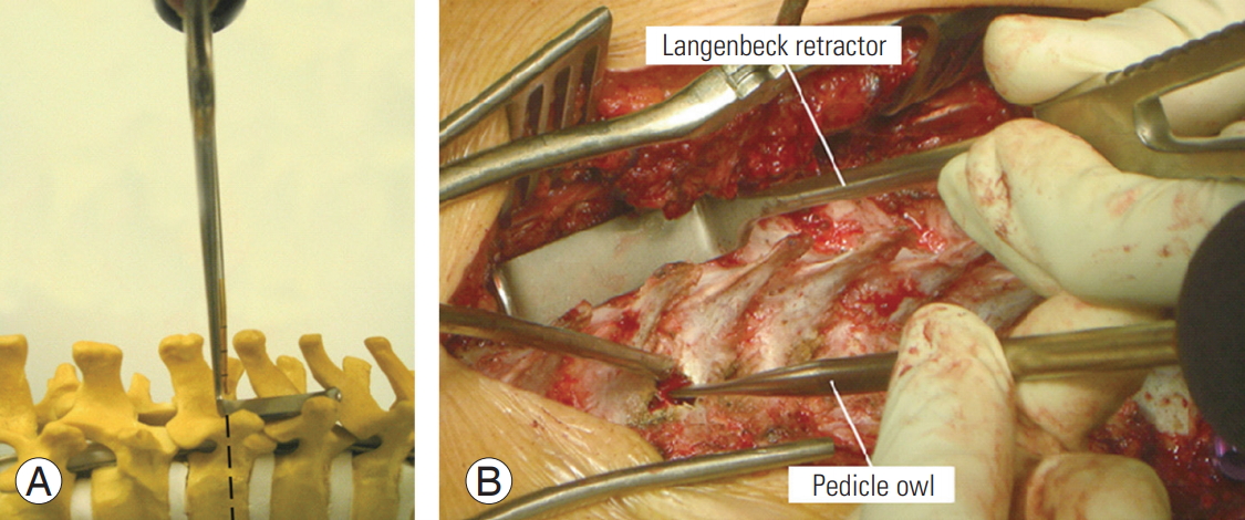
(A) Anatomical model showing the sagittal profile of the pedicle screw inclination of the vertebra. If a short-limb Langenbeck right-angle retractor is placed over the ipsilateral or contralateral posterior aspect of the inferior edges of the lamina above and the one to be screwed, the inclination of the long limb is to be followed during the insertion of pedicle screws to determine the sagittal inclination. The method was used for the placement of both lumbar and thoracic screws. (B) Intraoperative demonstration of the technique for determining the inclination of the pedicle screw.
The hypothesis of this study was that the pedicle axis (PA) is almost perpendicular to the ILL in the thoracic vertebrae. The objective of the study was to define the thoracic sagittal lamina–pedicle inclination and to estimate the safety zones for thoracic pedicle screw insertion. To the best of the authors’ knowledge, they are unaware of previous similar studies.
Materials and Methods
Due to the inherent difficulties and limitations in visualizing the lamina in the dorsal spine using X-rays, the measurements were performed via CT scans. Also, because of the unavailability of CT dorsal spine scans for normal individuals, CT chest scans of patients with no spinal pathologies (obtained for other indications between January 2017 and December 2017) were used for this purpose. Normal spine CT scans were selected by two spinal consultants at Spine Surgery Unit, Department of Orthopedics and Traumatology, Alexandria University. The three-dimensional curved multiplanar reconstruction (MPR) mode of the dorsal spine was constructed using the Horos software package (ver. 3.2.1 for Mac OSX; https://horosproject.org/).
This study’s protocol was approved by the Institutional Review Board and Ethics Committee (IRB approval no., 129-16). Informed consent was obtained from each patient.
All imaging studies were independently reviewed by two observers, both of whom were fellows with specific experience in spinal deformities. Each physician performed the measurements twice with a 1-week interval between measurements to determine the interobserver and intraobserver errors. Before the measurements, there was a comprehensive agreement on the methodology. Prior to the calculation of the measurements, the CT images were adjusted such that the axial cut was parallel to the upper endplate and the sagittal cut was perpendicular to the vertebral body (Fig. 2).
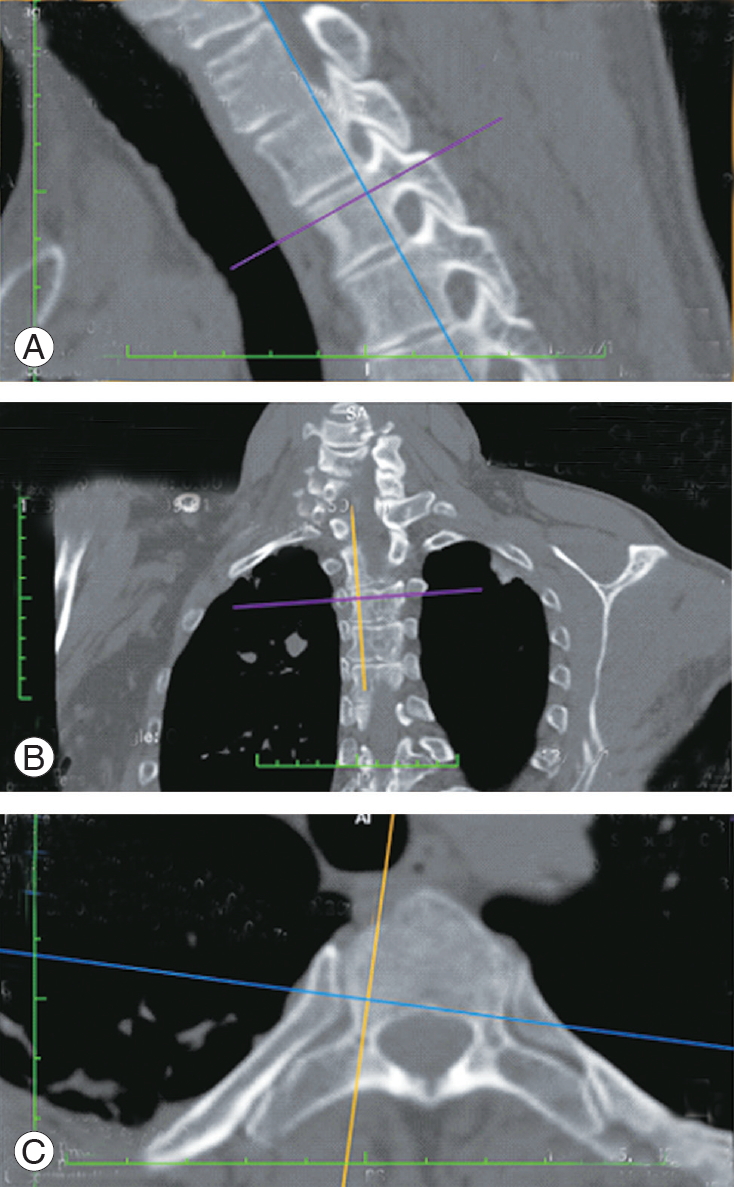
(A) Three-dimensional curved multiplanar reconstruction of a computed tomography chest scan. (A) The sagittal cut, (B) the coronal cut, and (C) the axial cut. The purple, blue, and orange lines indicate the orientation of the sagittal, coronal, and sagittal cuts. In this image, the axial and sagittal cuts are taken along the axis of the pedicle.
1. Steps
Step 1: A three-dimensional MPR mode using the Horos software (ver. 3.3.5; https://horosproject.org/) was created. The axial cut and the sagittal cut were taken through the axis of the pedicle (Fig. 2). The axis of the pedicle is the central cut between the pedicle walls in the axial and sagittal planes. In the sagittal plane, two lines were drawn; the first line was parallel to and passed through the upper endplate, whereas the second line was parallel to the first line and passed through the most cranial part of the inferior pedicle wall. The axis of the pedicle is a line parallel to the above two lines that passes through the middle (Fig. 3). Step 2: A screenshot of the sagittal cut was taken. Step 3: The sagittal cut (orange) was oriented perpendicular to the lamina and passed through its midpoint (Fig. 4). Step 4: A screenshot of the sagittal cut was taken. A tangential line connecting the lamina of the same vertebrae to the one above was drawn (ILL) (green) (Fig. 5). Step 5: Using the JPEG–DICOM plugin in the Horos software (https://horosproject.org/), Figs. 4 and 5 were converted to DICOM images and were opened within the software. Step 6: Using the image fusion function, the two images were superimposed (Fig. 6). The resulting image gives the orientation of the sagittal cut along the PA to the sagittal cut perpendicular to the lamina. The superimposed image appears as light yellow in color. Step 7: Definitions and measurements.
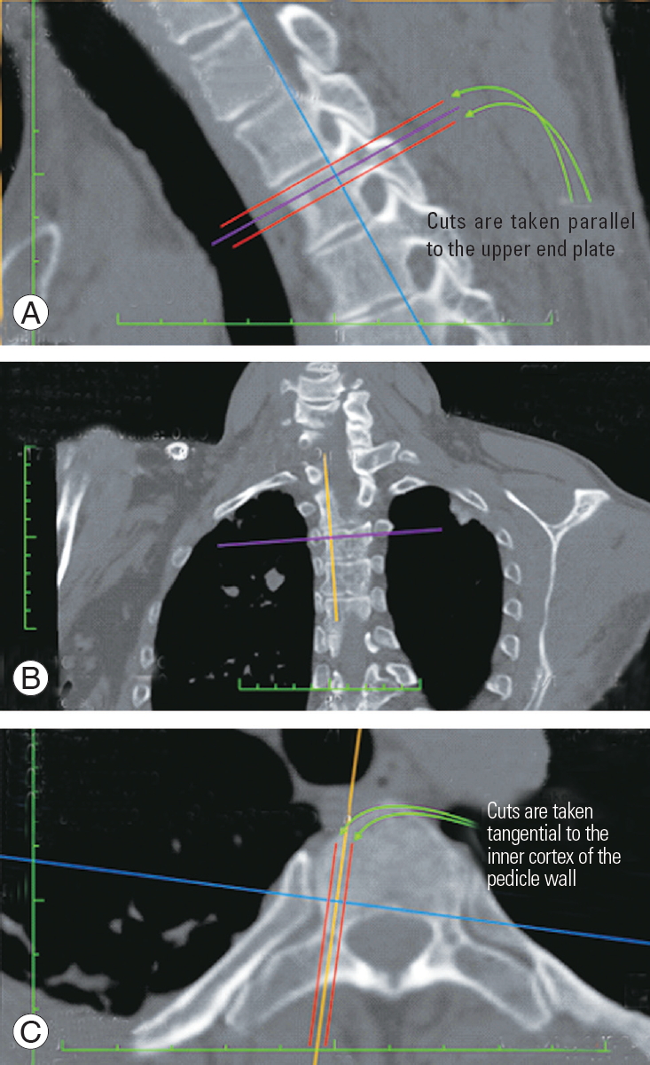
(A–C) The axis of the pedicle was selected by taking the middle of the two cuts tangential to the inner cortex of the pedicle walls in the axial and the sagittal planes. The red line indicates the cut tangential to the pedicle wall.
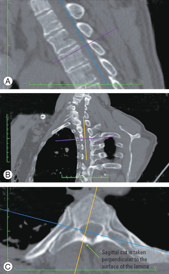
(A–C) The sagittal cut (orange) is oriented perpendicular to the lamina and passes through its midpoint.
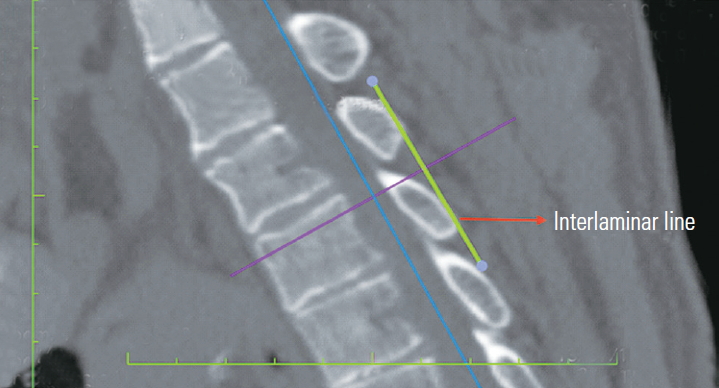
A screenshot of the sagittal cut of Fig. 3. A tangential line connecting the lamina of the same vertebrae to the one above is drawn (the interlaminar line).
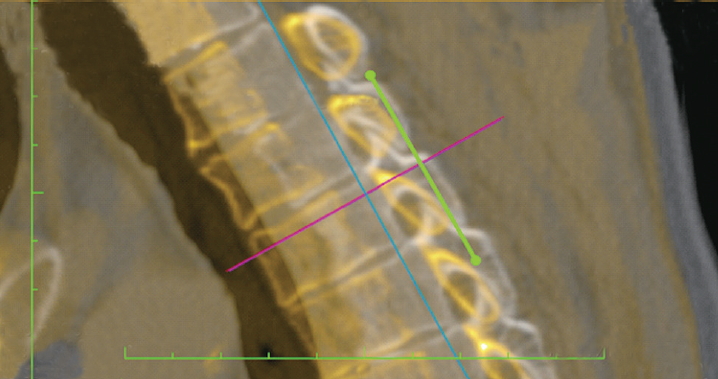
The two images were fused. This image gives the orientation of the sagittal cut along the pedicle axis to a sagittal cut perpendicular to the lamina.
2. Zones
Zone A: Upper 1/3 of the vertebral body (green). Zone B: Middle 1/3 of the vertebral body (yellow). Zone C: Lower 1/3 of the vertebral body (red); The exit zone of a line perpendicular to the ILL was noted. Any violation of the pedicle walls or the superior and inferior disc space was also observed (Fig. 7A).
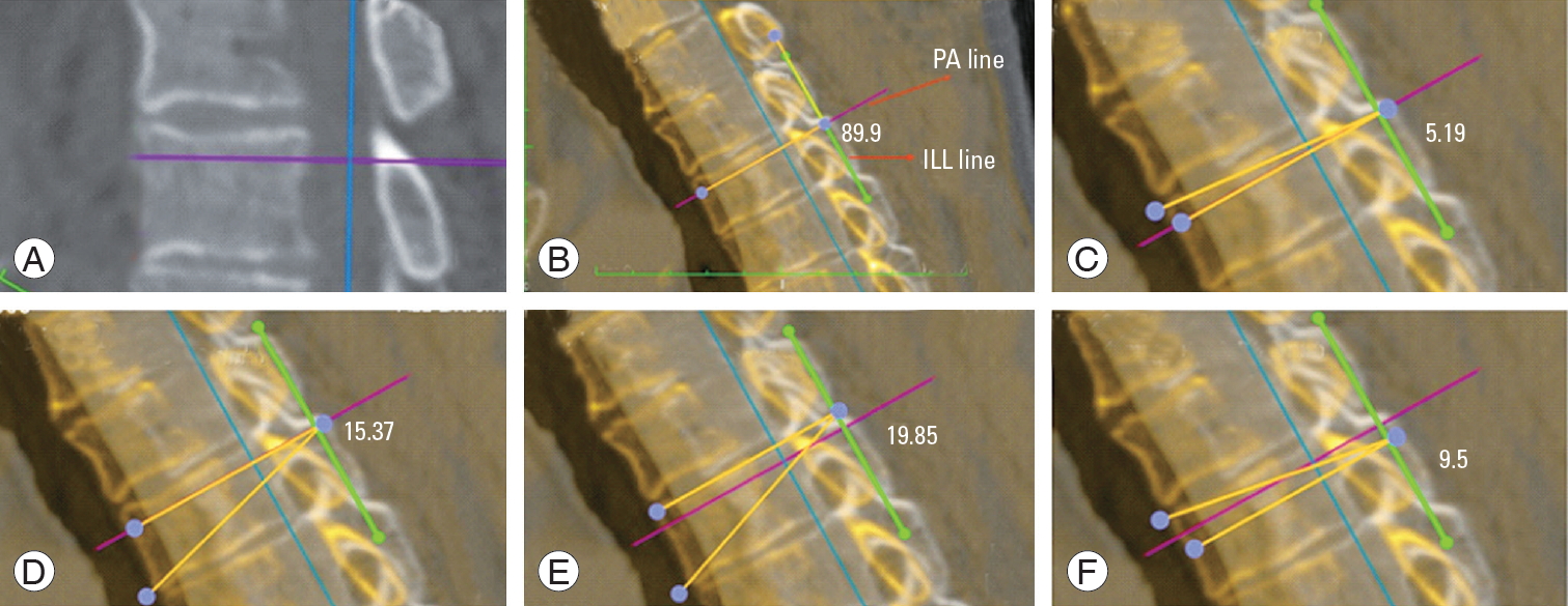
(A) Vertebral zones A, B, and C. (B) ILL–PA angle (ILL angle–PA angle). (C) Superior safe angle along the PA. (D) Inferior safe angle along the PA. (E) Inferior safe angle along the superior border of the pedicle. (F) Superior safe angle along the inferior border of the pedicle. ILL, interlaminar line; PA, pedicle axis.
3. Angles
The ILL–PA angle (Fig. 7B): the angle formed between the ILL and the PA line. The superior safe angle along the PA line (Fig. 7C): the angle formed between the PA line and the maximum cranial extent of the screw trajectory before violating the cranial pedicle wall or the superior endplate. The inferior safe angle along the PA line (Fig. 7D): the angle formed between the PA line and the maximum caudal extent of the screw trajectory before violating the caudal pedicle wall or the inferior endplate. The inferior safe angle along the superior border of the pedicle (Fig. 7E): the angle formed between a line parallel to the PA that passes through the cranial pedicle wall and the maximum caudal extent of the screw trajectory before violating the caudal pedicle wall or the inferior endplate. The superior safe angle along the inferior border of the pedicle (Fig. 7F): the angle formed between a line parallel to the PA that passes through the caudal pedicle wall and the maximum cranial extent of the screw trajectory before violating the cranial pedicle wall or the superior endplate.
4. Statistical analysis
Qualitative data were expressed as percentages and quantitative data as mean±standard deviation. Descriptive statistics were used for parameters that did not require statistical analysis. Pearson’s correlation test was conducted to determine the correlation between parameters. Interclass correlation coefficient (ICC) was used to determine the interobserver reliability. Microsoft Excel (Microsoft Corp., Redmond, WA, USA), SPSS software ver. 9.4 (SPSS Inc., Chicago, IL, USA), and GraphPad software (GraphPad Software, San Diego, CA, USA) were used for the analysis.
Results
The study material included CT chest images of 30 consecutive patients (20 males and 10 females) with a mean age of 49.87±15.48 years (range, 24–74 years). The mean kyphosis angle was 35.79°±9.68°. Interobserver reliability (ICC=0.85) and intraobserver reliability (ICC=0.8) exhibited good correlation; therefore, the mean of the two values was used. There was no significant difference between the measurements on the right and left sides (p=0.932).
1. Interlaminar line–pedicle axis angle
As presented in Table 1, the mean ILL–PA angle was almost orthogonal for all levels. The mean ILL–PA angle ranges between 86.21°±3.01° at D5 and 90.59°±2.72° at D10.

Interlaminar line–pedicle axis angle in various vertebrae
2. Inferior safe sagittal angle along the pedicle axis
Fig. 8A presents the mean safe sagittal angles along the PA for all levels before the violation of the caudal limits of the pedicle. Values range between 12.02°±2.51° at D4 and 15.26°±2.33° at D11.
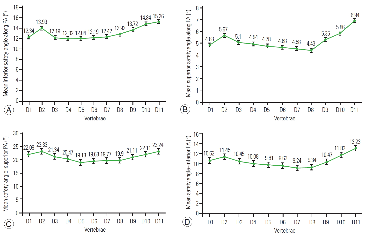
(A) Inferior safe sagittal angle along the PA. (B) Superior safe sagittal angle along the PA. (C) Inferior safe sagittal angle along the superior pedicle. (D) Superior safe sagittal angle along the inferior pedicle. PA, pedicle axis.
3. Superior safe sagittal angle along the pedicle axis
Fig. 8B presents the mean safe sagittal angles along the PA for all levels before the violation of cephalic limits of the pedicle. They range between 4.43°±0.75° at D8 and 6.94°±1.19° at D11.
4. Inferior safe sagittal angle along the superior pedicle
Fig. 8C presents the mean safe inferior sagittal angle along the superior pedicle before the violation of the caudal limit of the pedicle. The values are almost comparable and range between 19.13°±2.16° at D5 and 23.33°±2.76° at D2.
5. Superior safe sagittal angle along the inferior pedicle
Fig. 8D presents the mean safe sagittal angle along the superior pedicle before the violation of the cephalic limit of the pedicle. It is less than those along the superior pedicle and ranges between 9.24°±1.25° at D7 and 13.23°±2.04° at D11.
6. Vertebral exit zone
Table 2 presents that a line perpendicular to the ILL fell mostly into zone A. The data reveals that 97.67% (293/300) of the pedicle screw trajectories perpendicular to the ILL exited in zones A and B, and no trajectory violated either the pedicle wall (cranial–caudal) or the endplates.
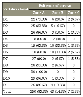
Exit zone of screw trajectories in various vertebrae
7. Correlation between thoracic kyphosis and the interlaminar line–pedicle axis angle in the various vertebrae
Applying Pearson’s correlation test, no connection could be found between both thoracic kyphosis and the ILL–PA angle. This means that the orthogonal concept is not affected by the thoracic sagittal profile; even in patients with different types of kyphosis, the PA maintains a constant relation with the ILL (Table 3).

Correlation between Interlaminar line–pedicle axis and the overall thoracic kyphosis angle in various vertebrae
Discussion
The purpose of this study was to prove the concept of perpendicularity of the thoracic pedicle over the lamina, the traditional habit upon which many spine surgeons depend in the sagittal inclination of the thoracic pedicle screw. Furthermore, the objective was also to assess the safe sagittal inclination of the thoracic pedicle screw before cephalic and caudal pedicle breach, which may lead to nerve root injury or to the intradiscal screw placement in addition to the loss of screw purchase (sagittal safety zone). The results confirmed the ILL–PA perpendicularity in the thoracic spine at all vertebral levels (T1–T11). This could have a significant surgical application facilitating the intraoperative sagittal inclination of freehand placement of thoracic pedicle screws. The recent similar study concerning the lumbar spine also proved the orthogonal concept at all lumbar levels, including T12 [16].
Few authors have reported that the freehand sagittal trajectory was orthogonal to the dorsal spine curvature. Fennell et al. [11] performed orthogonal sagittal inclination in 33 patients. However, detailed measurements of the individual vertebrae or the identification of vertebral zones were not analyzed. Furthermore, Oshina et al. [15] reported that the ideal sagittal trajectories for pedicle screw insertions were nearly orthogonal to the lamina surface or to the line connecting spinous processes. However, they were different for each vertebra, although the lamina surface method was most reliable for the C7–T1 vertebrae [15]. This series was limited to pedicle screws between C7 and T1. A study by Rivkin et al. [17] revealed that the sagittal trajectory was perpendicular to the long axis of the lamina. However, their studies were restricted to T1 pedicle screws. Recently, Kim et al. [18] exhibited that the sagittal angulation of the pedicle screw can be accurately predicted by directing it perpendicular to the superior articular process (SAP). This current study agrees with this technique; however, the facet joints can be involved in arthritic processes, and the orientation of the SAP could change. Conversely, the lamina is unaffected by arthritic changes in the spine.
Similar to the authors’ study on lumbar vertebrae, the majority (83.33%) of the pedicle screw trajectories perpendicular to the ILL in the thoracic spine in this series were positioned in zone A (located adjacent to the superior endplate) with only 2.33% in zone C. Cho et al. [19] reported that a trajectory parallel or caudal to the superior endplate can minimize screw breakage from repeated axial loading and that straight insertion of the pedicle screw in the midsagittal plane provides the strongest stability. This current study believes that the superior mechanical property of the straightforward technique was based on the fact that the screw engages more with the superior cortex of the pedicle and the compact cancellous bone along the superior endplate of the vertebral body. However, it should be noted that several other factors can affect pedicle screw stability, including sagittal and mediolateral inclination, the depth of screw insertion, and bone quality [20].
The concept of a safety zone of the mediolateral pedicle screw has been previously addressed [7]. However, the authors are unaware of any study concerning sagittal safety zones. To assess this, four different angles were measured to estimate the safety of sagittal pedicle screw inclination when inserting into the middle and the most cephalad and caudal parts of the pedicle. These angles are the superior and inferior safe angles along the PA, the superior safe angle along the superior pedicle, and the superior safe angle along the inferior pedicle. The results exhibited that the lowest safe angle was when the trajectory was directed cranially along the middle part of the pedicle, between 4.43°±0.75° at D8 and 6.94°±1.19° at D11. However, the inferior safe sagittal angle along the superior pedicle was the greatest and ranged between 19.73°±2.16° at D5 and 23.33°±2.76° at D2.
It should be noted that the authors do not recommend any new entry point for this technique. The entry point is the same as the ideal entry point along the PA. As such, the screw can be inserted perpendicular to the ILL. However, if the entry point is superior or inferior, the angulation must be changed accordingly. With a superior entry point, the angulation will be less than 90° and directed caudally, whereas with an inferior entry point, the angulation will be more than 90° and will be directed cranially to avoid violation of the pedicle walls. The main aim of defining the safe angle of pedicle screw insertion was to determine the range of angles possible with an entry point superior or inferior to the traditional entry point along the PA and along the superior or the inferior border of the pedicle, respectively.
The simple and clear information gained from the current study could be useful in the technique of open thoracic pedicle screw sagittal inclination through a better understanding of the direction in which pedicle screws should be inserted. This would minimize the application of fluoroscopy and the exposure to ionizing radiation without compromising the accuracy of screw insertion in the sagittal plane. Although this technique could be useful in the context of open techniques, this may not be useful or applicable in percutaneous image-guided methods.
This study was conducted on normal vertebrae with normal pedicles and could be applied in various spinal disorders, including traumatic and degenerative. As the lamina is unaffected by arthritic changes in the spine, degenerative spinal conditions should not change the orientation of the ILL.
Perpendicular screw placement is a matter of surgical experience. Stanescu et al. [14] measured the angle between the posterior aspect of the lamina and the PA by placing one arm of a goniometer on the posterior aspect of the lamina. The current study suggests using any simple right-angle instrument, such as Kocher-Langenbeck right-angle retractor, with the short arm placed over the posteroinferior edges of the two adjacent laminae. The sagittal inclination of the long limb of the retractor will then serve as a guide for the craniocaudal trajectory of the screw. This technique is novel, unique, and simple, with decreased potential for human error, and could be used in the lumbar and thoracic spine in various spinal disorders.
Inserting screws in the thoracic vertebrae is relatively straightforward. However, it can sometimes be complicated in deformities, such as kyphosis. Many novice surgeons often use repeated lateral C-arm shoots to guide the sagittal trajectory of the screws. This technique may provide the surgeon a good visual cue and can limit the use of fluoroscopy and the exposure to ionizing radiation. It should also be noted that the ILL–PA perpendicularity concept does not work or requires modification when there are changes in the vertebral body shape. (Vertebral wedging in Scheuermann’s kyphosis is an example.)
There are few limitations to the current study. The sample size is small; if it were expanded, it would give more weight and reliability to the study. This study was conducted on normal patients with normal spinal anatomies. The use of this technique in deformed spines requires further research. The mediolateral inclination, which is usually the more difficult part, was beyond the scope of this study.
Conclusions
The results of this study confirmed the ILL–PA perpendicularity in the thoracic spine at all levels. The ILL is a useful guide for pedicle screw sagittal inclination. Moreover, the results revealed that the inferior safe sagittal angle along the superior pedicle was the greatest. Therefore, the sagittal trajectory during thoracic screw placement could be safer if the entry point is through the superior part of the pedicle.
Notes
No potential conflict of interest relevant to this article was reported.
Author Contributions
Study design: TE, NDP; writing the manuscript: TE; radiographic assessment: NDP, MEF; statistical analysis: NDP; provision of the concept, the data interpretation, and critical review: KDL; and manuscript preparation and critical review: DS.