


Introduction
Spinal radicular pain is caused by compression or irritation of the spinal nerve or its root. Treatment options range from conservative management to surgical interventions. The conservative methods include drug prescription and physiotherapy [1-3]. Surgical management, nevertheless, is sought for patients with failed conservative treatment and with saddle anesthesia, loss of bladder or bowel sphincter control, and remarkable neurological deficits. Transforaminal injection (TFI) is a well-established, minimally invasive, and commonly performed procedure for spinal radicular pain. It is performed under fluoroscopy or computed tomography (CT) because of needle tip visualization and dye spread delineation [4-7]. Nevertheless, its major disadvantages are radiation exposure of patients, doctors, and support staff, requirement of a specialized area to perform the intervention, expensive equipment, and wearing uncomfortable heavy lead aprons.
In recent years, ultrasound (US)-guided nerve blocks have gained attention as it offers several advantages than those performed with fluoroscopy or CT, such as no radiation exposure, no requirement of a separate area to perform the block, equipment mobility, and visualization of soft tissue and real-time needle trajectory [8]. Although US has proved reliable and accurate for spinal injections, such as epidural injections, median branch block, and facet joint injections, description of US-guided transforaminal injection (USTFI) is scarce [8-10]. This is mainly because of shadowing of the foraminal area with the bony structures, and thus, nonvisualization of the final needle tip position at the desired location. Nevertheless, owing to the advantages of US-guided blocks, a few authors have attempted to describe USTFI [11-18].
The purpose of this article is to illustrate all the described techniques of USTFI in the literature to evaluate its current evidence.
Methods
This narrative review included all published materials illustrating technical aspects of lumbar USTFI. Lumbar selective nerve block (SNRB), performed as a diagnostic procedure for nerve root pain with similar technical procedure as that of TFIs, was also included [19-23]. PubMed, Embase, and EBSCO were searched for relevant literature using combinations of keywords, such as US, US-guided, sonography, lumbar, TFI, periradicular injection, pararadicular injection, and selective nerve root block. Literature was checked from January 1, 2000, to May 31, 2019. Only original research articles, case studies, or case series published in English language were included. The references of the articles were also searched to identify additional relevant publications. Studies describing US nonlumbar radiculopathy and nonlumbar SNRB were excluded as they involve dissimilar technical procedures. Review articles on USTFI and US-guided SNRB illustrating previously described technical aspects were also not included.
The articles were classified on the basis of the probe orientation, axial, parasagittal (PS), or a combination of the two, in the performance of the block. The articles were evaluated regarding the following factors: cadaver or human studies, needle alignment, comparison of USTFI to other techniques, like fluoroscopy or CT, use of dye for confirmation, dye spread pattern, and other complications. The results of the published data were lastly evaluated for current evidence on USTFI.
Results
A total of seven original research papers and one case report on lumbar USTFI and five articles on US-guided SNRB were found and included (Table 1). There were no non-English articles found. The technical aspects of the procedure are described subsequently on the basis of the probe orientation.
1. Axial approach
Axial approach is defined as the placement of the US transducer perpendicular to the long axis of the body.
1) USTFI
A total of three studies described the axial approach for USTFI, two of which were in cadavers in in-plane (IP) needle trajectory with curvilinear probe [11,13]. The human study was by Wan et al. [17], the only study that compared axial approach to PS approach.
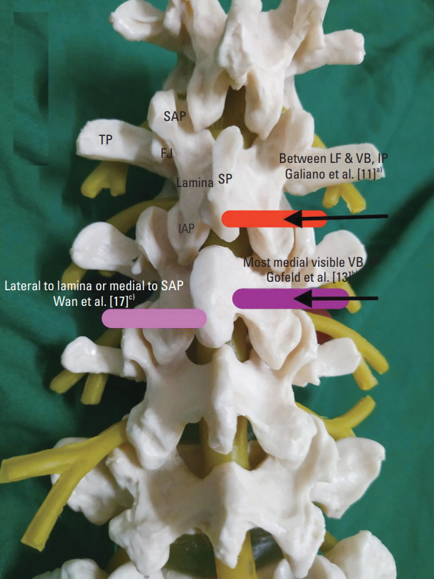
First description of axial USTFI was in 2005 by Galiano et al. [11]. A total of ten lumbar USTFI in a single cadaver were performed. After identifying the desired spinal level in sagittal US image, a curvilinear transducer was placed axially to view the spinous process and adjacent structures (vertebral arch lamina, zygapophyseal articulations, inferior and superior facets, transverse process, and vertebral isthmus). The gap between the superior articular facet and vertebral body was considered as the space where the spinal nerves lie. The needle was inserted IP toward the spinal nerve and stopped at this dorsal foraminal opening. The needle tip was confirmed with axial CT with dye spread, which showed dorsal foraminal dye spread. All the needle tips were placed within the dorsal third of the intervertebral foramen in periradicular area. Difficulty was encountered in accurately depicting the periradicular area in the upper lumbar spine (L1–L3) as it is where, according to the authors, vertebral arch lamina is narrower, space between transverse processes is small, and appearance of vertebral isthmus is like a straight fissure (Table 2, Fig. 1).
The other research on axial approach was also a cadaver study published after 8 years in 2012 by Gofeld et al. [13]. The authors argued that in the previously described technique, because the needle tip was placed dorsally and laterally to neural foramina, it was unlikely that the injectate would extend to the ventral epidural compartment, which is the desired location for effective block. Moreover, the technique could cause an inadvertent needle placement in the neuraxial compartment because as the needle tip approaches the articular process level, its further progress is shadowed by the bony structures. Therefore, the authors placed the probe axially to view the spinous process, lamina, and vertebral body. The needle was inserted IP aiming at the most medially visible shadow of vertebral body rather than the previously described injection space between the lateral facet and the transverse process. The needle was stopped when it hit the bone. Dye confirmation with this technique revealed favorable needle tip location at the ventral part of the intervertebral foramen in 91.7% of the cadavers, with more intraforaminal contrast spread than extraforaminal (42 versus 4) (Table 2, Fig. 1).
First human study in axial orientation was by Wan et al. [17] in 2017. The authors placed a curvilinear US probe over the spinous process in transverse axial scan to visualize the spinous process, lamina, facet joints, and transverse process. Then, a 22G needle was inserted IP to reach the lateral side of the lamina or medial to superior articular process, at Z joint location. Confirmation was done by CT scan. This approach was compared with the PS approach [17].
2) US-guided SNRB
A total of three reports described the technique in axial orientation of curvilinear probe. Chumnanvej et al. in 2011 [20] and 2017 [22] performed US-guided SNRB, similar with the technique of Gofeld et al. [13], by hitting most of the medial part of the vertebral body. In both studies, the needle tip confirmation was through contrast and fluoroscopy. Mei et al. [23] in 2019 described US-guided SNRB with the same technique in patients posted for knee or hip replacement. Nevertheless, the needle tip was checked with fluoroscopy without dye.
2. Parasagittal approach
PS approach is defined when a US transducer is placed parallel to the body’s long axis.
1) USTFI
A total of four studies and one case report have described this approach, of which three involved human and one a cadaver, and all used curvilinear probe and IP needle trajectory [12,14-17] (Table 2, Fig. 2).
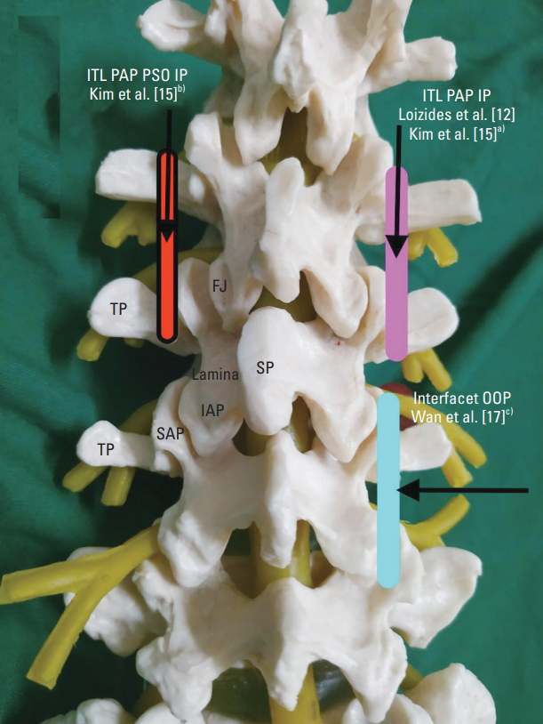
The first description of this approach was in cadavers by Loizides et al. [12] in 2011. The authors performed 10 US-guided injections at five different levels (L1–L5). After localization of the desired spinal level, the transducer was moved laterally in the PS orientation from the vertebral arch to the zygapophyseal joints. Then, the transducer was further advanced laterally until a trident sign of the transverse processes was just seen and then moved back toward the midline until the edge of the zygapophyseal joint was viewed again. In this final scanning plane, called as the pararadicular aditus plane (PAP), the intertransverse ligament (ITL) was seen as a thin hyperechoic band between the two adjacent transverse processes. Spinal nerves, if identifiable, were seen in PAP, ventral to the ITL as a slightly hypoechoic roundish structure surrounded by hyperechoic fat. A 22G spinal needle was inserted using free-hand IP technique at desired level under real-time US guidance. The authors advanced the needle tip until it reached the respective ITL advancing the needle barely through it. The authors proposed this approach to be easy to perform as ITL is an easily identifiable US landmark even in upper lumbar spine. Dye confirmation on CT revealed that all the needle placements are in the right space.
The authors later confirmed the same technique in human patients in 2013 and compared it with CT [14]. A total of 40 adult patients were consecutively enrolled and categorized either to the US group or CT group. The needle tip position in the US group was verified by CT without dye confirmation. The accuracy of the US procedure was 90%. Similar pain relief was seen in both techniques. The authors concluded that US-guided pararadicular injections result in a remarkable reduction in procedure time and expenditure and radiation avoidance.
Kim et al. [15] in 2015 conducted a human study on USTFI with dye spread confirmation. They compared two groups. In PS group, USTFI was performed with the methodology described by Loizides et al. [12], that is to view ITL in PAP in PS scan and to pass the needle just through it. In the other group, they used the parasagittal oblique (PSO) approach, wherein the probe was tilted 20°–25° medially after reaching the end point of the PS group. The PSO technique revealed favorable results, with the needle tip placed deeper and more medially than the PS group and remarkably more intraforaminal dye spread and pain relief (Table 2, Fig. 1).
Wan et al. [17] in 2017 compared the axial approach with the PS approach. The axial approach was as described previously. For the PS approach, a PS scan was performed until edges of zygapophysial joints were visualized. A 22G out of plane (OOP) needle was inserted at 70° from the skin to place the needle tip between the adjacent facet joints. No report on ITL visualization in PAP was stated as in the previous techniques. None of the patients faced any treatment-related side effects. Reported success ratio of this study was 95%. The authors concluded that to deposit the medication close to the nerve root, the PS OOP approach is better than the axial IP approach (Table 2, Fig. 1).
In 2016, a case report by Ahn et al. [16] described lumbar root block in a pregnant patient with worsening radicular pain. US-guided PSO approach was used, as described by Kim et al. [15], but the patient was placed on lateral decubitus position. No confirmation by dye spread was performed, but remarkable pain relief was achieved on follow-up at 2 months.
2) US-guided SNRB
Two studies described PS approach for USTFI. Sato et al. [19] in 2009 performed the block at the transverse process of L5 with a nerve stimulator needle in OOP needle trajectory. Kim et al. [21] in 2013 performed US-guided SNRB by first performing a medial branch block (MBB) in axial probe orientation with the IP needle, and then in the PS scan, US-guided SNRB was performed by inserting the OOP needle at the same angle and depth as the in situ needles, which had been inserted for MBB.
3. Combination of axial and parasagittal orientations of probe
1) USTFI
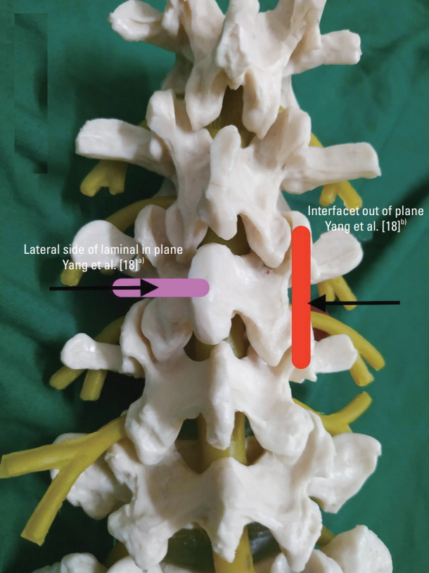
Yang et al. [18] in 2018 combined axial and PS probe orientations for USTFI in human patients (Table 2, Fig. 3). First, an axial scan with a linear probe was performed to view the spinous process, lamina, facet joint, and transverse process. Then, the IP needle was inserted toward the lateral part of the lamina. The probe was then turned 90° for PS orientation, to confirm the needle to be in the middle of the adjacent facets. The needle was moved out a little, slipped beside the lamina, and advanced a little inside until no resistance was felt. The success rate of USTFI by this technique was 85%. Operation time in the US group was remarkably shorter than that in fluoroscopy group with lower radiation dosage. No remarkable difference in pain relief and no major complications were observed between both groups. As this technique was based on lamina visualization, the authors proposed remarkable challenge in the upper lumbar spine. To overcome needle tip shadowing by the bony structures, especially when it passed below the lamina, the authors emphasized loss of resistance (LOR) technique as further progress might lead to permanent damage to the neuraxial structures. (Table 1, Fig. 1). Dye confirmation was not performed in this study. The main drawback of the study was inclusion of patients with body mass index (BMI) less than 25.0 kg/m2.
Discussion
The study on USTFI was first described in cadavers in 2005 [11]. The first human report of lumbar USTFI was described in 2013, and the first report on US lumbar SNRB was described in 2009 [14,19].
1. Cadaver versus human studies
Of the eight reports, three described cadavers, of which two were in axial and one in PS US probe orientation [11-13]. Axial probe orientation for USTFI was described in only one human study [17]. Of the four studies that used PS probe orientation, three were in humans and one in cadavers [12,14-16]. The combined approach of USTFI is described only in humans [18]. All studies on US-guided SNRB were on humans [19-23].
Implication: Although cadaver studies are marvelous in exploring a new technical approach, its validation requires human studies. In this regard, PS approach of USTFI takes an upper edge presently.
2. Axial versus parasagittal orientation of the ultrasound probe
Of the seven articles and one case report published on lumbar USTFI, three articles described axial orientation, four articles and one case report described PS orientation, and one study described combination of axial and PS orientations of US probe [11-18]. In US-guided SNRB, three and two studies utilized transverse and PS orientation, respectively [19-23].
Implication: The authors have explored both axial and PS approaches for USTFI. Nevertheless, many of the studies in the last 5 years were about the PS approach. This could be because of ease of ITL identification even in upper spine and older patients.
3. Probe used
In all the studies except one, a curvilinear probe was used [11-17,19-23]. All patients included by Yang et al. [18], who used the linear probe, were of low BMI. In all the studies, lumbar vertebra identification was performed by placing the subjects (cadaver or patient) in prone position followed by a midline sagittal scan to visualize typical transition of the first sacral to the fifth lumbar spinous process. Cephalad counting was done to identify the desired level followed by USTFI either in PS or axial approach.
Implication: Owing to deep location of the lumbar spine, a curvilinear probe is best suited for the procedure.
4. Delineation of structures at final ultrasound scan to perform the block
In axial scan, in one study of Gofeld et al. [13], final US image delineated the spinal process, lamina, and vertebral body. In one study of Galiano et al. [11], final US image delineated the spinous process, lamina, superior articular process, gap below, and vertebral body. In two studies of Wan et al. [17] and Yang et al. [18], the final US image of axial scan included spinous process, lamina, and transverse process. In PS scan, three studies identified PAP between adjacent transverse processes for USTFI [12,14,15]. One study did not rely on PAP identification but kept the probe between adjacent ZP joints [17].
Implication: Notably, in the axial approach, various authors have explored different final US images before performing the block. This is largely because of the nonvisualization of needle tip at the foraminal area owing to the bony structures. No study, until date, has compared the different technical approaches of axial USTFI, making it difficult to conclude the best technical approach. Nevertheless, there is consistency in the described technical procedure of PS USTFI, which is almost similar in all the studies.
5. Needle used
A quincke spinal needle was used in all the studies in the performance of the block [11-23]. Largely for cadaver studies, a 20G needle was used, and for human studies, a 22G needle was employed.
Implication: A quincke spinal needle can be utilized for both axial and PS approaches in USTFI.
6. In-plane or out of plane needle trajectory
Most of the studies performed USTFI in IP needle trajectory [11-16,18,20-23]. Only Wan et al. [17] employed OOP in PS for USTFI. Sato et al. [19] employed OOP in US-guided SNRB.
Implication: Current evidence points toward performing USTFI in IP needle trajectory in both axial and PS approaches largely because of needle path visualization and non-exploration of OOP approach.
7. Final needle tip position
Final needle tip in axial USTFI was described at different end points in the studies: dorsal foraminal opening in the space between lateral facet and transverse process [11], on medial part of vertebral body [13], and at lateral part of lamina or lateral part of narrowest part of lamina [17,18]. In PS approach, needle placement was almost similar in all the studies, that is to place it through the ITL [12,14-18].
Implication: In axial USTFI, the authors have identified possible neuraxial injury owing to needle tip nonvisualization at the final location. To overcome this drawback, Gofeld et al. [13] placed the needle at the vertebral body than in the desired “space.” Yang et al. [18] described seeking LOR to identify the desired location but recognized that needle placement in the paraspinal space could give false positive results.
8. Confirmation of needle tip
In the eight published articles on USTFI, final needle tip position was confirmed by CT in four studies and by fluoroscopy in three studies [14-18,20,21]. One case report did not confirm needle position as it was performed on a pregnant patient [16].
Implication: All studies on USTFI have confirmed needle tip position by another standard technique (fluoroscopy or CT), which implies that quality studies have been conducted to explore USTFI.
9. Dye spread for needle tip confirmation
Presence of dye spread in ventral intraforaminal space is the most ideal to determine successful TFI. Nevertheless, only Kim et al. [15] investigated dye spread in human patients in PS and PSO techniques. Two cadaver studies (Loizides et al. [12] and Gofeld et al. [13]) utilized dye confirmation; one each in axial and PS approaches. All but one study on US-guided SNRB used dye and fluoroscopic confirmation of needle tip [19-22]. One study utilized only fluoroscopic confirmation [23].
Implication: Human dye spread studies in either of the two approaches of USTFI are scarce in literature. Future studies in this regard are recommended for a more definitive deduction on the most suitable technical procedure. With the current evidence, no conclusion can be made regarding this.
10. Trials comparing ultrasound-guided transforaminal injection with other radiological guidance
Only two studies compared lumbar USTFI with other radiological guidance [14,18]. In one study by Loizides et al. [14], lumbar USTFI was compared with CT-guided techniques. In another study by Yang et al. [18], lumbar USTFI was compared with fluoroscopy technique. None of the studies on US-guided SNRB compared it with the other techniques [19-23].
Implication: Randomized trials are most suited to determine superiority or inferiority of a new technique to an established technique. In this regard, more studies are recommended to validate USTFI.
11. Complications
No authors observed any major complication of USTFI and US-guided SNRB, although intravascular patterns were seen in two studies, one each in cadaver and human patients [13,15].
Critical analysis of the above-mentioned studies reveals that although the first description of USTFI was in 2005, only a few studies were published in the last 15 years. The main issue, especially in axial USTFI, is nonvisualization of the needle tip at the desired location as it is covered by the bony structures. This may cause undesired inadvertent neuraxial injury. Another disadvantage of axial USTFI is its technical difficulty in the upper spine owing to the short lamina as almost all techniques rely on its identification. Probably for this reason, in the last 5 years, almost all studies on USTFI have explored the PS approach, which seems to be technically easier and is homogenously described in its technical aspects. Moreover, in PS USTFI, ITL delineation is easy even in the upper spine. The main concern appears to be lack of clear guidelines on needle advancement beyond ITL. Few studies have stated the needle to “just go beyond ITL” [24]. Another concern was inability for identification of traversing nerve roots deep in the ITL, which may lie in the needle path [24].
USTFI might also be a challenge in old people [18]. Yang et al. [18] attributed USTFI failure in older patients to muscle degeneration and increased muscle mass intensity, which make structural delineation on an US challenging. Thus, more studies are needed in this age group, to determine its technical feasibility.
Conclusions
The main advantage of USTFI is lesser radiation exposure, which is invaluable in certain groups of patients, like pregnant patients with nerve root pain. At present, USTFI confirmation with fluoroscopy seems essential.
From the present data, a definitive conclusion for the best technique of USTFI cannot be drawn. Further studies with larger sample size and description of dye spread patterns are recommended to come to a more definite conclusion.