


Introduction
Cervical pedicle screw (CPS) fixation is a widely accepted treatment option for cervical instability brought about by traumatic, congenital, infectious, neoplastic, and degenerative disorders. It offers several advantages that include a high fusion rate and long-term stability [1,2]. However, the use of CPS fixation has been limited by several factors, including the need for technical skill and the risks associated with the complex neurovascular structures surrounding the cervical pedicle, particularly in the atlantoaxial (C1–C2) cervical region [3,4]. Iatrogenic injury to these structures caused by faulty pedicle screw fixation could pose a significant impact on the patients’ function and overall outcomes [3–8]. Hence, the accuracy in the placement of screws in the axial cervical spine plays a vital role in both the clinical and biomechanical success of the procedure [7,9]. In line with this, there is an undeniable need to develop methods to improve the accuracy of pedicle screw placement to avoid or reduce potential complications [10–12]. Conventionally, the reliance on anatomical landmarks has been fraught with issues of anatomical variations [5,13]. The visual obstruction caused by Mayfield head holders, which are commonly used when performing surgeries over the axial cervical region, limits the standard use of intraoperative fluoroscopy [14], and the effectivity of image-guided navigation is limited by the unstable anchorage of navigational arrays on the small and compact posterior elements of the axial cervical region [15].
In the recent decade, attention has been given to three-dimensional (3D) printing techniques to create drill guide templates for cervical spine stabilization. In cadaveric and clinical studies for the subaxial (C3–C7) cervical region, it has been shown that the use of stereolithographic drill guide templates is feasible and has accuracy rates of 91% to 94% [16]. Despite the possible advantages of this procedure, there is little literature on the use of a patient-specific template in the axial (C1–C2) cervical region of the spine and more so for CPS insertion [17,18]. Clinical series studies of Kaneyama et al. [19] and Sugawara et al. [20] are noteworthy because they have already used 3D printed surgical templates in the axial region to insert screws primarily into the lateral masses. CPS insertion in the axial region has always been a challenge because of the structural complexity of the atlantoaxial cervical spine and the extremes of anatomical variation rendered by the course of the vertebral artery.
Given the biomechanical advantage that CPS insertion can provide when stabilizing the C1–C2 vertebrae, it is critical to determine whether a similar strategy will produce the same level of accuracy. In this study, we will use stereolithographic 3D modeling to create patient-specific surgical templates using a novel technique previously described [16], and we will assess the accuracy of CPS fixation in the atlantoaxial cervical vertebrae using the hand molded template.
By establishing the accuracy of cadaveric studies, this study may establish foundations for further research and clinical applications of the use of the patient-specific surgical template in atlantoaxial CPS fixation. In response to the Unified Health Research Agenda 2017–2022 on Global Competitiveness and Innovation in Health, specifically on the development of biomedical products and engineering, the findings of this study are critical in developing an accurate yet cost effective technique for treating atlantoaxial spinal injuries. This will benefit both surgeons and patients in a low-resource setting, particularly since 3D printers are already very affordable nowadays.
The objective of this study is to evaluate the use of a patient-specific drill guide template for pedicle screw insertion into the atlantoaxial cervical spine using desktop stereolithographic modeling. The study’s specific goal is to determine the accuracy of atlantoaxial CPS insertion on cadaveric specimens using the Gertzbein and Robbins classification system for transpedicular screw placement [21].
Materials and Methods
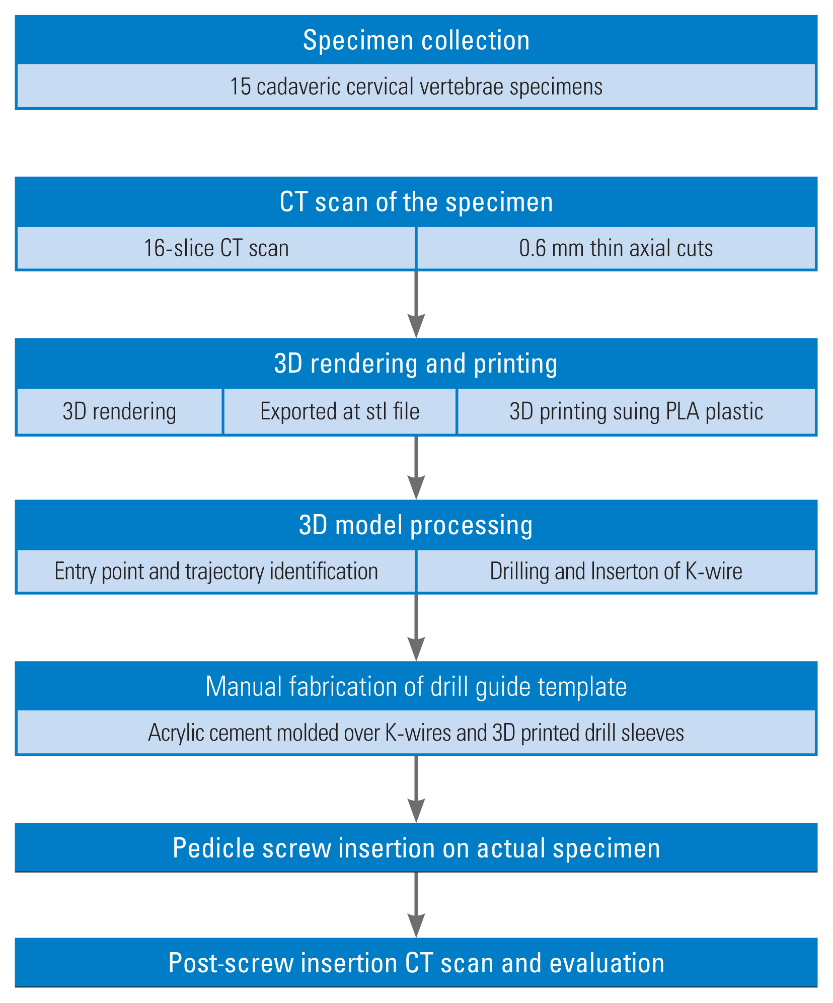
This study was conducted following the principles described in the Declaration of Helsinki. The use of cadaver specimens was approved by the college of medicine and the study’s protocol was reviewed and approved by the University of the Philippines-Philippine Manila Research Ethics Board (UPMREB Code: 2020–242-EX, April 29, 2020). Fig. 1 summarizes methodology from specimen collection to post C1–C2 pedicle screw fixation evaluation.
1. Specimen collection
Fifteen sets of atlantoaxial cervical vertebra specimens were collected from the Department of Anatomy, College of Medicine, University of the Philippines Manila. The collected cervical specimens belonged to seven males and eight females with an average age of 49.36 years (range, 24–69 years) (Appendix 1). Informed consent was waived because the specimens were drawn from a pool of abandoned and anonymous cadavers.
A computed tomography (CT) scan of the specimens was obtained using a GE Discovery Helical 16 slice CTScan machine (GE Healthcare, Chicago, IL, USA) from the Department of Radiology, Philippine General Hospital, University of the Philippines Manila. Digital Imaging and Communications in Medicine (DICOM) images of the specimens were produced. Thin axial sections of 0.6-mm thickness were taken to produce DICOM images of our specimen. The CT DICOM images of the atlantoaxial spine were loaded into a DICOM reader which is a Horos (Horos Project, Annapolis, MD, USA), a free open-source medical free software application. The latter was used to isolate the C1 and C2 vertebrae from the rest of the subaxial cervical spine by digital subtraction to produce 3D rendered digital images of all C1 and C2 specimens. The final 3D rendered digital images were converted and exported as a stereolithographic file (stl), which was the format used for 3D printing of the cervical models.
2. Production of biomodels and surgical drill templates
The exported “stl” files of the atlantoaxial cervical spine were loaded into an Ultimaker 2 desktop 3D printer (Ultimaker, Zaltbommel, Netherlands), which was used to print a 1:1 scale 3D replica of all atlantoaxial cervical vertebra specimens using polylactic acid plastic and the fused deposition method. Thirty axial cervical vertebrae were printed from 15 cadaveric spines (15 atlas vertebrae [C1] and 15 axis vertebrae [C2]).
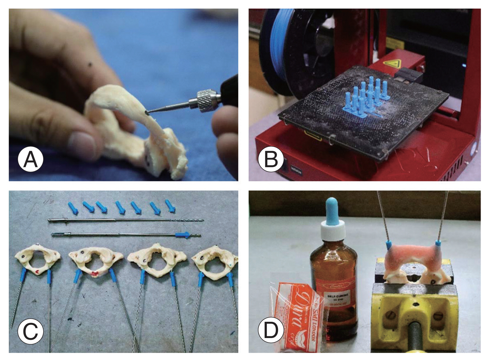
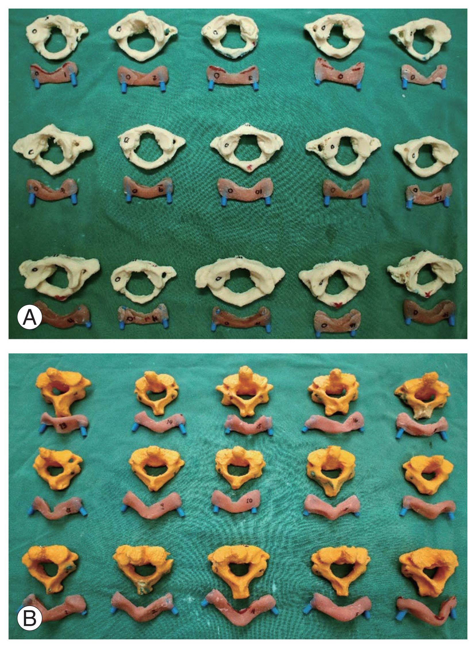
Fig. 2 shows the template fabrication process. Using a 2.0-mm drill bit, a hole was drilled into the desired entry point of the lamina as it would be done in actual surgery. A 2.0-mm K-wire was then inserted through the pedicles of the 3D printed specimen in a postero–anterior direction. The trajectory was carefully chosen such that the wire fell at the center of the pedicle in all planes—axial, sagittal, and coronal. To serve as the drill sleeve for a 2.3-mm cervical drill bit, a 3D printed screw sleeve guide (18 mm length×3 mm inner diameter×5 mm outer diameter) was inserted into the K-wire and incorporated. To incorporate the bilateral K-wire inserted in the models with the plastic drill sleeves, a mixture of fast setting and self-curing dental polymethylmethacrylate powder and the liquid polymer was molded over the posterior elements of the 3D printed models. Latter was allowed to set for 5 minutes and removed after another 2 minutes to provide us with the drill jig templates for all C1 and C2 specimens (Fig. 3).
3. Cadaveric cervical pedicle screw insertion
All cadaver specimens were prepared by removing the soft tissues attached to the posterior elements. This simulated the subperiosteal dissection performed during actual posterior cervical instrumentation. The drill jigs were anchored to the cadaveric specimens to ensure the best possible snug and fit. A click or snap is usually felt or heard when the template snaps to sit squarely on the posterior elements of the atlantoaxial cervical vertebrae. If this click or snap is not heard or seen, it must be removed to check whether any soft tissues are on the way. When the template is flushed against the bone with no movement superiorly or inferiorly, it is ready for drilling.
Fig. 4 illustrates the steps of the insertion of pedicle screws. An awl was inserted in the jig to mark the entry point of the cervical screws. The jig was then removed. To ensure a smooth entry of the cervical drill bit, the entry point was scored with a burr. The jig was reapplied, and the drilling was completed with a 2.3-mm cervical drill bit. The drilled hole was tapped and the pedicle screw was installed. Either 3.5- or 4.5-mm diameter (depending on availability) GLOBUS cervical screws (Global Medical Inc., Audubon, PA, USA) were used.
4. Evaluation of pedicle screw insertion accuracy
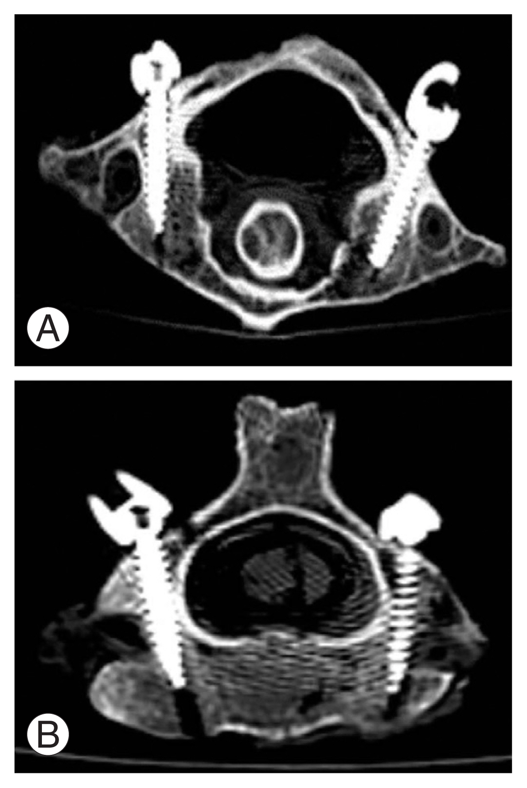
Fig. 5 shows an example of a post-CPS insertion CT scan done for each of the 15 cervical specimens using 0.6-mm CT cuts for each of the C1 and C2 instrumented cadaveric. The accuracy was assessed using the Gertzbein and Robbins classification system and the axial CT scan images are shown in Table 1. Using the aforementioned classification system, an independent senior spine consultant who was not involved in the 3D printing of the cadaveric models, drill jig fabrication, or screw insertion evaluated the images for breach sites. Grades A and B are considered acceptable. On the other hand, grades C to E were considered unacceptable since they were associated with problematic clinical outcomes postscrew insertion. Appendix 2 contains a tabulated grading of the accuracy of CPS placement using patient-specific drill jigs.
Results
A total of 60 pedicles (combined C1 and C2) from 15 cadaveric axial cervical vertebrae were evaluated. We found that the use of a patient-specific drill guide template in pedicle screw insertion in the atlantoaxial cervical vertebrae had a total accuracy rate of 95% (57/60). An accuracy rate of 100% was achieved for C1 while an acceptable accuracy rate of 90% was achieved for C2. The study’s findings are summarized in Table 2. No breach was observed on the C1 vertebrae. All breaches (4/60) were found in the C2 vertebrae, one graded B (acceptable) and three others graded C (unacceptable). All breaches occurred in the foramen transversarium. Upon review of the screws used, all C2 vertebra breaches were inserted with 4.0-mm pedicle screws. Breaches would have been acceptable if 3.5-mm diameter screws were used instead.
Discussion
The outcomes of this study showed a 95% acceptable accuracy rate for atlantoaxial CPS insertion using a patient-specific drill guide template. It is worth noting; however, that all screw insertions in cadaveric C1 vertebrae resulted in no pedicle cortice breach. C2 pedicle screw insertion, on the other hand, resulted in a 10% breach rate, which was unacceptable. This difference in accuracy rates between C1 and C2 is attributed to pedicle screw size and anatomical variance between C1 and C2.
On a closer look at the screw sizes used in the study, all C2 specimens were instrumented with 4.0-mm pedicle screws. In the review of various literature on pedicle screw fixation in the atlantoaxial spine, the standard screw size used is 3.5 mm [2–7]. The decision to use 4.0-mm screws was made primarily due to the lack of available 3.5-mm screws, which is a limitation of this study; it is possible that if 3.5-mm screws had been used for C2, a significant breach could have been avoided. Furthermore, in a study by Lee et al. [22] in 2011, screw insertion in C2 pedicles resulted in more malposition, indicating that the accuracy is more challenged in C2 pedicles than in C1.
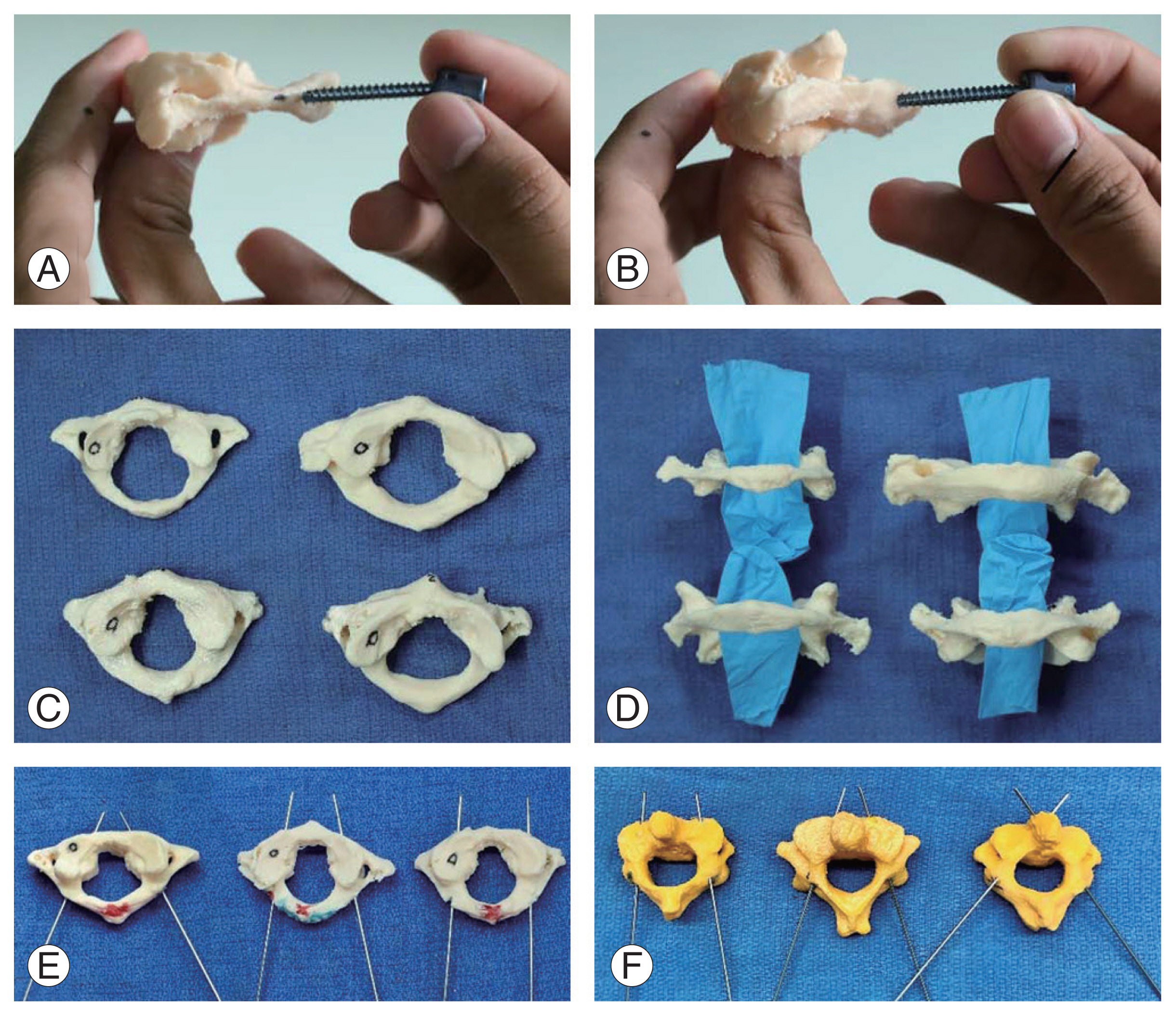
The accuracy of a hand molded patient-specific drill guide would lie on (1) direct visualization of the morphometry of the cervical pedicles and careful insertion of K-wires and (2) meticulous molding of acrylic cement on the cervical models [16]. Throughout this study, we will highlight several pearls and pitfalls. Fig. 6 depicts the most noticeable differences that were discovered.
The variations in the morphometry of C1 and C2 vertebrae must be carefully examined to be able to select the correct entry point and trajectory for pin placement. One trap would be to try to achieve symmetry by patterning the pin placement to the contralateral side. Pedicle’s direction is not always a direct mirror image of its contralateral counterpart. As a result, attempting to follow the K-trajectory wires to the contralateral side may result in a breach out of the pedicle cortex. Fig. 7 shows the difference in the trajectory of the pedicles of a C2 vertebra model and the breach within the foramen transversarium even just after insertion of a K-wire.
It is for a special reason why spine specialists treat the axial spine quite differently from the subaxial cervical spine region [3–5,8,9]. The course of the vertebral artery causes many anatomical variations, and we discovered that the pedicle anatomy in the axial region is not a mirror image based on the limited specimen we used. As a result, anatomical landmarks will be the least reliable basis for CPS insertion. Fluoroscopy will still be a standard tool in ascertaining our CPS trajectory intraoperatively, more so if one has the luxury of a translucent Mayfield head holder. But the footprint it provides to give us a biplanar view of our CPS trajectory creates maneuverability issues for the many surgeons as well. Image-guided navigation is truly a game-changer if your center possesses this expensive equipment. Even so, the axial spine region is so small and fragile that even if the small and fragile posterior elements of the axial cervical region can accommodate the placement of navigational arrays, the insertion of CPS is still technically challenging. Nowadays, robotic surgery has shown significant and superlative accuracy in pedicle screw fixation compared to surgical templating and image-guided surgery over the thoracolumbar region [23]. Robotic surgery, on the other hand, is very expensive and is still a long way from becoming a standard tool in most surgical centers. Much remains to be desired in terms of its applicability in CPS insertion, particularly in the axial cervical region.
The patient-specific drill guide template technique, as described in this paper, is a promising surgical technique in the management of atlantoaxial instability for CPS insertion. Its use also reduces radiation exposure among surgeons, patients, nurses, and other operating room personnel. The application of this technique in resource-constrained countries may provide a more cost effective method of applying CPS for atlantoaxial stabilization. With the novel technique we reported in 2017, we previously elaborated on the economics of 3Dprinted surgical guides or templates [16]. This is even more practicable nowadays as the price of 3D printers has now become more accessible and affordable.
The limitations of the study include the following: (1) the number of 3.5-mm pedicle screws available for the study was limited; and (2) because the cervical vertebrae were extracted from the cadaver, the insertion of pedicle screws does not completely simulate the actual insertion process experienced in real live surgeries at the axial cervical region.
Conclusions
Patient-specific drill guide template using stereolithographic modeling is accurate in the pedicle screw insertion of cadaveric atlantoaxial specimens. However, more research is needed to better assess the accuracy of insertion in C2 pedicles. Furthermore, the insertion of pedicle screws on actual, nonextracted cadaveric cervical specimens may be performed to better simulate clinical practice conditions such as positioning and surgical exposure.