A Novel Trajectory of C7 Laminar Screws Determined Using Three-Dimensional Computed Tomography and Surgical Simulation Software: Comparison with a Pre-existing Trajectory
Article information

Abstract
Study Design
Examination using three-dimensional screw trajectory software and computed tomographic scans.
Purpose
To evaluate the feasibility of a novel trajectory for C7 laminar screws and to compare it with an old trajectory.
Overview of Literature
The previously reported trajectory of C7 laminar screws has a horizontal direction without a fixed target point. Our new trajectory has a cephalad direction with a fixed target point.
Methods
Computed tomographic scans of a total of 50 male and 50 female patients were utilized. The placement of C7 laminar screws was activated employing the new and old trajectories. The success rate, the causes of failure, and the maximum allowable length of each trajectory were compared.
Results
Employing the new trajectory, the success rates of the unilaminar and bilaminar screws were 93% and 83%, respectively, which were significantly better than the old trajectory (80%, p<0.0001 and 70%, p=0.0003). The most prevalent cause of failure was laminar cortical breach followed by facet joint violation. The new trajectory also offered significantly longer maximum allowable screw length in unilaminar (32.5±4.3 mm vs. 26.5±2.6 mm, p<0.001), bilaminar cephalic (29.5±3.8 mm vs. 25.9±2.6 mm, p<0.0001) and bilaminar caudal (33.1±2.6 mm vs. 25.8±3.1 mm, p<0.001) screws than the old trajectory. With the new and old trajectories, 70% vs. 6% of unilaminar, 60% vs. 2% of bilaminar caudal, and 32% vs. 4% of bilaminar cephalic screws could be protracted perfectly into the corresponding lateral mass without any laminar cortical or facet joint violation (p<0.0001).
Conclusions
The novel trajectory possesses a substantially higher success rate, longer maximum allowable screw length, and higher chance to be extended into the lateral mass (a condition known as a lamino-lateral mass screw) than the old trajectory.
Introduction
Lateral mass and pedicle screws is typically preferred for fixation in posterior subaxial cervical arthrodesis [1–3]. Nevertheless, at the C7 vertebra, several problems may be encountered by the lateral mass and the pedicle screws such as instrumentation failure, technical difficulty, limited accessibility, and vasculature risk [4–7]. Hence, C7 laminar screw has been introduced as a potentially safe alternative [8–10]. There are various advantages of employing a C7 laminar screw. First, it is biomechanically stronger than the lateral mass screw [9] and some research even reported that it is as strong as the pedicle screw [9,11,12]. Second, because it can be inserted under direct vision of the lamina and all the significant structures [13], it is technically simpler and does not need the application of a fluoroscopic or navigational guide [7]. Third, in cases where the vertebral artery courses in the C7 transverse foramen, it avoids the risk of arterial damage during pedicle screw placement [7].
A laminar screw simply involves the placement of a polyaxial screw from the spinolaminar junction into the contralateral lamina. Only a few pieces of literature describe the trajectory of the C7 laminar screw [7,10,14], which is commonly horizontal in direction, following the slope of the lamina, into the midportion of the lamina. However, to our best knowledge, none of these pieces of literature precisely described the best or optimal entry and target points of the C7 laminar screw. Hence, the purpose of this study was (1) to define a novel trajectory for C7 laminar screw with a fixed target point, (2) to evaluate the feasibility of the C7 laminar screw employing the novel trajectory, and (3) to compare it with the old trajectory [15].
Materials and Methods
1. Inclusion and exclusion criteria
This study was approved by the institutional review board of Seoul National University Bundang Hospital (B-1604-344-112). Considering the retrospective nature of this investigation and the use of anonymized patient data, the requirement for informed consent was waived. Cervical spine computed tomography (CT) scans with 1.0-mm intervals (Mx8000, IDT; Philips Medical System, Best, the Netherlands) carried out in a single institution from January 2012 to December 2015 were initially included in this study for the examination. The exclusion criteria were patients younger than 20 years, poor quality CT images, postoperative scans, and the presence of pathology which distorts the anatomy of the vertebra including trauma, infection, tumor, and congenital anomalies. One hundred patients (50 of each sex) were chosen from those who satisfied the selection criteria.
2. Computer simulation
The axial CT scan images of those chosen patients were converted into a three-dimensional (3D) model employing simulation software (VWorks; Cybermed Inc., Reston, VA, USA). This software simultaneously enabled the adjustment of screw entry point and trajectory by referring to multi-planar images and 3D images (Fig. 1). Unilaminar and bilaminar screw placement was activated utilizing the new and old trajectories.

Screw placement using three-dimensional software is shown.
3. Screw trajectories
In the new trajectory, the entry point for the unilaminar screw was positioned at the craniocaudally midpoint of the spinolaminar junction. The screw’s trajectory followed the axis of the contralateral lamina, with its direction aiming toward the center of the cranial lateral quadrant of the opposite lateral mass that is, the target point (Fig. 2). Six imaginary lines were drawn to determine the target point. The three vertical lines were shaped by (1) the lateral border of the lateral mass, (2) the junction between the lamina and the lateral mass, and (3) a bisecting line between the two lines. The three horizontal lines were established by (1) the facet joint line of C6–7 as the cranial line, (2) the facet joint line of C7–T1 as the caudal line, and (3) a bisecting line between the two lines (Fig. 2).

For the novel trajectory, the entry point for unilaminar screw is at the midpoint of spinolaminar junction. The target point is the center of the cranial lateral quadrant of the opposite lateral mass.
The entry point for the cephalic screw was positioned at the cranial third of the spinolaminar junction for bilaminar screws, while the caudal screw was sited at the caudal third of the junction (Fig. 1). These entry points had to be modified craniocaudally to accommodate bilateral screws. Both the cephalic and caudal screws were directed to the target points similar to the unilaminar screws (Fig. 2). With the target point fixed, the entry points and trajectories of both screws were modified numerous times to prevent screw collision, laminar cortical breach, and facet violation during simulation. The priority was always to prevent screw collision.
Regarding the old trajectory, the description of the trajectory by Shin et al. [14] was most comprehensive so that we could exactly replicate their trajectory. Additionally, their description appeared to represent the previous descriptions of the trajectory. Therefore, we chose their description. The entry point for the unilaminar screw was positioned at the craniocaudally midpoint of the spinolaminar junction and the trajectory followed the slope of the contralateral lamina but the direction was directed at the craniocaudally middle portion of the lamina. Hence, the trajectory was horizontal in direction. For bilaminar screws, the entry points for both cephalic and caudal screws were placed cranially and caudally, respectively. The differences from the new trajectory were that (1) the trajectory of the cephalic screw was focused slightly on the caudad to be positioned in the midpoint of the lamina, and (2) the trajectory of the caudal screw was directed slightly toward the cephalad (Fig. 3).

In the old trajectory, the cephalic screw was aimed slightly caudad to the craniocaudally midpoint of the contralateral lamina while the caudal screw was directed slightly cephalad.
4. Screw dimension
The diameter of 4.0-mm and the initial length of 24 mm was the screw’s dimension. A 4.0-mm diameter was chosen to enable a 0.5-mm safety margin for 3.5-mm screws in live surgery whereby decortications of the lamina are often performed to create a fusion bed.
5. Evaluation of the feasibility
The feasibility of the laminar screw placement was assessed for laminar cortical breach and facet joint violation (Fig. 4). Laminar cortical breach was described as any violation of the outer cortex by the screw. Facet joint violation was defined as the tip of a 24-mm screw violated the facet joint. Screw placement was considered successful when laminar cortical breach and facet joint violation was absent for a 24-mm screw. The success rate of the laminar screw placement both new and old trajectories was analyzed and compared.

Two causes of failure are shown: laminar cortical breach (black arrowhead) and violation of the facet joint (white arrowhead).
6. Maximum allowable screw length
The maximum lengths of the screws were quantified only if the placement of the laminar screw was successful. Starting from the initial length of 24 mm, the length of the screw gradually increased with a 2-mm increment (like a real screw length increment). The length just before the breach was considered the maximum allowable length. The average lengths of the unilaminar, bilaminar cephalic, and bilaminar caudal screws of both trajectories were computed and compared.
7. Lamino-lateral mass screw
During the simulation, we discovered that in some cases C7 laminar screws might project beyond the lamina into the lateral cortex of the lateral mass, without any laminar cortical breach and/or facet joint violation (Fig. 5). We named it as lamino-lateral mass screw. The number of cases in which lamino-lateral mass screws were feasible was measured for each of the new and old trajectories and compared.

The novel trajectory allows the laminar screw to extend into the lateral mass without any violation of the laminar cortex or facet joint.
8. Statistical analysis
McNemar test was employed to compare the success rate of screw placement, causes of failure, and incidence of the lamino-lateral mass screws between the two trajectories. Paired t-test was utilized to compare the maximum allowable screw length. All statistical analyzes were carried out utilizing Stata/MP ver. 17.0 (Stata Corp., College Station, TX, USA). The level of significance was set at p<0.05 for all statistical analyzes.
Results
1. Demographic data
One hundred subjects (50 males and 50 females) with an average age of 40.8 years (range, 20–65 years), were enrolled in this research. Each subject had 8 laminar screw simulations, that is., two unilaminar (right and left side) and two bilaminar (both sides simultaneously) screws activated by using the new trajectory and then repeated employing the old trajectory. Hence, a total of 800 screws were activated.
2. Success rate of C7 laminar screws
The success rate of new and old trajectories of C7 laminar screws is displayed in Table 1. The overall success rate for the new trajectory was 93% for unilaminar and 83% for bilaminar screws. They both were significantly higher than the old trajectory (80% for unilaminar and 70% for bilaminar) with p<0.0001 and p=0.0003, respectively. The new trajectory also exhibited a higher success rate for both males and females (p<0.05).
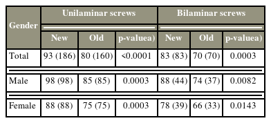
The success rate of new and old trajectories of C7 laminar screws
3. The causes of screw failure
The causes of laminar screw failure are summarized (Table 2). Most of the failures in both new and old trajectories were triggered by the laminar cortical breach. In unilaminar screw failure, the new trajectory possessed a lower laminar cortical breach rate and facet joint violation rate as compared to the old trajectory (p<0.05). In bilaminar screw failure, the new trajectory had a lower facet joint violation rate and the rate of concurrent laminar cortical and facet joint violation (p<0.05).
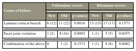
The causes of C7 laminar screw failure
4. The maximum allowable screw length
The illustrates maximum allowable screw length for C7 laminar screws is illustrated in Table 3. Utilizing the new trajectory, the average maximum length was 32.5±4.3 mm for unilaminar screws, 29.5±3.8 mm for bilaminar cephalic screws, and 33.1±2.6 mm for the bilaminar caudal screw. The unilaminar screw and both bilaminar screws were significantly longer with the new trajectory as compared to the old trajectory (p<0.0001).
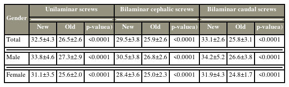
The maximal allowable screw length for C7 laminar screws
5. Lamino-lateral mass screws
The incidence of the lamino-lateral mass screw is summarized. The new trajectory had a significantly higher chance to position a lamino-lateral mass screw than the old trajectory: 70% versus 6% (p<0.0001) for unilaminar screws, 34% versus 4% (p<0.0001) for the bilaminar cephalic screws, and 60% versus 2% (p<0.0001) for the bilaminar caudal screws.
Discussion
Laminar screw is reported as a potentially safe alternative to lateral mass and pedicle screws for C7 fixation [8–10]. Several terminologies have been utilized by different authors to determine this screw placement, such as the laminar, crossing-laminar, translaminar, and intralaminar screws [7,10,11,14]. The screw is positioned from the spinolaminar junction toward the contralateral lamina. Nevertheless, the descriptions of the exact trajectory in these pieces of literature were unclear. Alvin et al. [10] briefly described the trajectory to be directed venterolaterally from the screw entry point through the contralateral lamina. Hong et al. [7] utilized an entry point at the base of the spinous process and the screw trajectory was created along the junction between the middle and inferior third of the C7 lamina. Shin et al. [14] utilized the entry point at the spinolaminar junction whereby, the entry point for the caudal screw was placed close to the caudal margin of the lamina and the entry point for the cephalic screw was positioned more cranially. The trajectory of the caudal screw was placed approximately parallel to the inclination of the caudal margin of the opposite lamina, whereas the cephalic screw was kept slightly caudad to place it into the thicker portion of the lamina [14]. Conversely, the trajectory could still take several pathways because there was no fixed target point.
In the present research, the new trajectory had a similar entry point as in the prior reports mentioned above but a fixed target point for the trajectory was positioned at the center of the cranial lateral quadrant of the opposite lateral mass. This trajectory generally presents a cranially directed screw pathway as compared to the prior reports. This novel trajectory is technically similar to any of the previous trajectories in real surgery. It does not necessitate further dissection to determine the anatomical landmark for the target point. With a standard method of posterior surgery to the C7 region, the borders of the lateral mass of C7 can be determined and palpated easily employing a Penfield dissector, without dissection of the facet joint capsule.
This research demonstrated that the new trajectory is better than the old trajectory in success rate and maximum allowable screw length. The success rate of the new trajectory was significantly higher than the old trajectory in both unilaminar and bilaminar screws (Table 1). Morphometric research of the cervical spine demonstrated that the thickest portion of the lamina is found in the middle portion [15]. Because the lateral portion of the C7 lamina is more cranially positioned than the medial portion, the upward direction of the new trajectory has a better chance to prevent the thinner part of the lamina. The lateral masses are sited more cranially than the midline structures as well. The new trajectory screws in a similar direction as the anatomical orientation are less likely to violate the C7–T1 facet joints.
The new trajectory offered a significantly longer maximum allowable screw length than the old trajectory in both unilaminar and bilaminar screw addition (Table 3). The new trajectory has a more upward projection than the old trajectory, which is more horizontal. Hence, the screws in the new trajectory travel longer lengths within the lamina than in the old trajectory. Additionally, when the new trajectory met perfectly with the anatomical orientation of the corresponding lateral mass and facet joint, it enabled the laminar screw to project beyond the lamina into the full diagonal width of the lateral mass till its lateral cortex, without any violation of the laminar cortex or facet joint; a condition that we proposed the term lamino-lateral mass screw (Fig. 5). This further elevated the maximum allowable screw length. The new trajectory has a significantly higher chance to place a lamino-lateral mass screw than the old trajectory (Table 4). The amino-lateral mass screw might potentially pose a better biomechanical profile than the laminar screw with this added length of fixation into the lateral mass. These outcomes may be valuable clinically when a strong construct is required for the correction of fixed deformity, osteoporotic spine, and reconstruction following tumor resection.

The occurrence of lamino-lateral mass screws
Because of the longest screw purchase, the bilaminar caudal screw offers a longer allowable screw length than the unilaminar screw because the former has a more caudal starting point than the latter while they both possess cranial direction. Thus, even for unilaminar screw fixation, bilaminar caudal screw trajectory will provide a longer screw purchase. Nevertheless, the difference in the allowable screw length between the two trajectories is only 0.6 mm on average so it is not significant clinically. Additionally, if the caudal end of the fixation/fusion is at C7, a more caudal entry point with a more cranial direction of the trajectory may cause less convenient surgical procedures needing fighting against the muscles and other soft tissues. Alternatively, in cases with longer incisions such as in cases with fixation extending to the upper thoracic levels, it would be beneficial to select the trajectory of the bilaminar caudal screws. The choice between the two trajectories depends on the operating surgeon’s case by case.
Like in any other study, this research has its limitations. First, we could alter and adjust the entry points numerous times during simulation but in real surgery, only a single attempt would be permitted in most cases. So, the present research probably overestimated the success rate. Second, this research did not consider the viscoelasticity of the lamina. Pedicle expansion has been reported to occur in 85% of the patients in whom the screw diameter surpassed 65% of the pedicle outer diameter [16]. Lamina could possess similar or greater expansion during screw placement and might enable a higher success rate than this research. Finally, this study was not supported by any biomechanical testing.
Conclusions
In conclusion, the new trajectory has a significantly higher success rate and longer maximum allowable screw length than the old trajectory in both unilaminar and bilaminar screws of C7. Additionally, the new trajectory has a significantly higher chance to be protracted into the lateral mass (lamino-lateral mass screw) than the old trajectory.
Notes
Conflict of Interest
No potential conflict of interest relevant to this article was reported.
Funding
This study was supported by a research grant of Seoul National University Bundang Hospital (grant number: 14-2016-021).
Author Contributions
Conceptualization: JSY; data curation: CKL, QYL, BW; formal analysis: JP, SMP; funding acquisition: JSY; methodology: HJK, BSC; project administration: JSY; visualization: CKL, QYL; writing–original draft: JSY; writing–review & editing: SMP, JSY; and final approval of the manuscript: all authors.