C2 Superior Facetal Osteotomy: A Novel Technique in Complex Craniovertebral Junction Surgery for C1 Lateral Mass Screw Placement
Article information

Abstract
Complex craniovertebral junction (CVJ) defects account for a considerable proportion of CVJ diseases. Given the heavily assimilated C1, an unfavorable C1–C2 joint orientation, an overriding C2 superior facet, a low-hanging occiput, and an abnormal vertebral artery course with a high-riding vertebral artery, placement of C1 lateral mass screws might be difficult. To address this, a novel technique for placing C1 lateral mass screws that avoid vertebral artery injury, low-hanging occiput, and overriding C2 superior facet was developed in this study. This approach enables firm fixation of C1–C2 even in difficult situations where the placement of the C1 lateral mass is challenging.
Introduction
Complex craniovertebral junction (CVJ) anomalies account for a considerable share of CVJ disorders. Most of them have an assimilated C1 (atlas, C1A), a hypoplastic C1 lateral mass (C1 LM), an unfavorable C1–C2 joint orientation, platybasia, atlantoaxial dislocation (AAD) with a rotating component, a bone abnormality with thin C2 pedicles, and an aberrant vertebral artery (VA) course with a high-riding VA (HRVA). These difficulties are regarded as challenging surgical conditions. Several alternatives for C2 screw placement are available [1]; however, the same cannot be true for C1-LM screws. Despite limited choices for C1 fixation, C1-LM screws have been employed mostly owing to the consistent anatomy of the C1 LM; however, this may not be always true in patients with complex CVJ.
Difficult C1-LM screw placement is a critical concern, particularly in C1A when the C1 LM is buried deeply in the joint space with high-riding C2 pedicles, impeding the trajectory of the C1-LM screws by the overhanging occiput in extremely narrow C1–C2 joint space. The presence of anomalous VA further deters the dissection of the C1–C2 joint. In these instances, occipitocervical fusion (OCF) becomes a viable alternative, although its biomechanical stability, degree of movement, fusion rate, and technical simplicity are inferior to those of C1–C2 fusion approaches reported by the Goel-Harms technique [2].
Herein, we will go present the technical subtleties of a unique C2 superior facetal osteotomy for the placement of C1-LM screws in a patient with AAD where the anatomy of the C1 LM, C1–C2 joint orientation, and VA course compelled us to employ it.
Technical Note
1. Surgical technique
1) Ethical statement
This study was conducted in compliance with the principles of the Declaration of Helsinki. Institutional review board approval was not necessary for this study. Written informed consent was obtained from the patient(s).
2) Surgical indications
This technique is useful for treatment of complex CVJ anomalies where there is assimilated C1, an unfavorable C1–C2 joint orientation, AAD with a rotating component, and an aberrant VA course impeding the trajectory of the C1-LM screw, overhanging occiput in extremely narrow C1–C2 joint space, and deeply buried C1 LM.
3) Preoperative evaluation/patient setting
Magnetic resonance imaging (MRI) and computed tomography (CT) scans of CVJ were performed. MRI provided information about the degree of cord compression, associated myelopathy, Chiari malformations, or syringomyelia. CT helps in determining the degree of AAD and basilar invagination (BI), screw size, screw trajectory, occiput positioning, and degree of C2 superior facetectomy needed. All cases needed preoperative cervical traction to stabilize the cervical spine intraoperative rather than achieve reduction.
4) Surgical procedures
Following general anesthesia and intubation, the patient was placed prone on the operating table. A horseshoe headrest was placed as a head support. Cervical traction was employed to stabilize the neck. A midline neck incision was made starting from the inion to the C4 spinous process, with meticulous midline dissection, exposing the underside of the occiput, C1 posterior arch, and C2 lamina. C2 pedicles and superior faces on both sides were exposed with subperiosteal dissection according to methods reported by Goel et al. [3].
The superior facet of the axis overhanging the C1–C2 joint space is identified as shown in Fig. 1A and 1B. If an abnormal VA is coursing through the joints, it can be protected using Penfield no. 4 dissector on the upper border of the superior facet. A high-speed drill with a 2-mm diamond burr is currently used to drill away a portion of the C2 superior facet (Fig. 1C). Drilling the whole depth of the superior facet of C2 exposes the C1–C2 joint below and medial to the anomalous VA and C2 nerve root. This maneuver obviates the need for VA mobilization and C2 nerve root sacrifice, and as the operator is away from the epidural space, it significantly reduces the chances of torrential venous bleeding.

Schematic diagram of the technique of C2 subfacetal osteotomy. (A) C1–C2 joint space with overhanging superior facet of C2 along with low-lying occiput obscuring the joint space. (B) Area of C2 superior subfacetal osteotomy (marked in the green bordered area). It can be seen that it’s difficult to place the planned C1-lateral mass screw. (C) So, a high-speed motorized drill is used to make the osteotomy after the osteotomy of the marked area. (D) Placement of planned C1-lateral mass screw after C2 subfacetal osteotomy.
After exposure, the joint space is prepared, and a C1 lateral mass screw is inserted in standard fashion (Fig. 1D). As the lower part of the C1–C2 joint is exposed, the entry point of the C1 LM is lower than standard exposure; thus, the C1-LM direction is more cranially oriented than the standard orientation. Fluoroscopy was used to guide the placement of a screw with a diameter of 3.5 mm and maximum length of 24±4 mm. C1-LM screws were inserted, and C2 pedicle/pars/subfacetal/translaminar screws were placed using standard techniques by the possible morphology of the C2 vertebra [1]. AAD was reduced using the method by Goel and Kulkarni [4]. Bony decompression was performed after screw implantation, if necessary.
5) Postoperative care
The patient is transferred to the postoperative ward with a hard cervical collar. The patient is mobilized with the help of the physiotherapy team and was discharged within postoperative days 5–10. The patient is advised to wear a hard cervical collar for 6 months and then undergo scanning to assess the degree of fusion.
2. Case description
1) Case 1
A 16-year-old male patient complained of neck discomfort and limb weakness over the previous 2 months. For the past 15 days, he has been unable to walk. He had no history of trauma. He was found to have spastic quadriparesis (Medical Research Council [MRC] grade 3/5 in all four limbs) during neurological evaluation. Brisk deep tendon reflexes were observed at all main joints. Bilateral extensor plantar reflexes were noted. Hoffmann sign was positive on both sides. Spastic weakness in the bowels and bladder was observed. The breath-holding period was 12 seconds, and sensory modalities remained unaltered. On admission, the patient’s modified Japanese Orthopedic Association (mJOA) score was 10/18.
MRI of the CVJ showed compression and myelomalacial changes in the CVJ region (Fig. 2A). The midsagittal section of CT image of the CVJ showed BI with AAD (Fig. 2B). Parasagittal CT section through the C1–C2 facet joints showed the C1 LM placed deep and covered by overhanging C2 superior facets and pedicles posteriorly (Fig. 2C). CT angiography of the neck vessels with three-dimensional (3D) reconstruction showed bilateral fenestrated VA coursing posterior to the C1–C2 joint space on both sides (Fig. 2D–F).
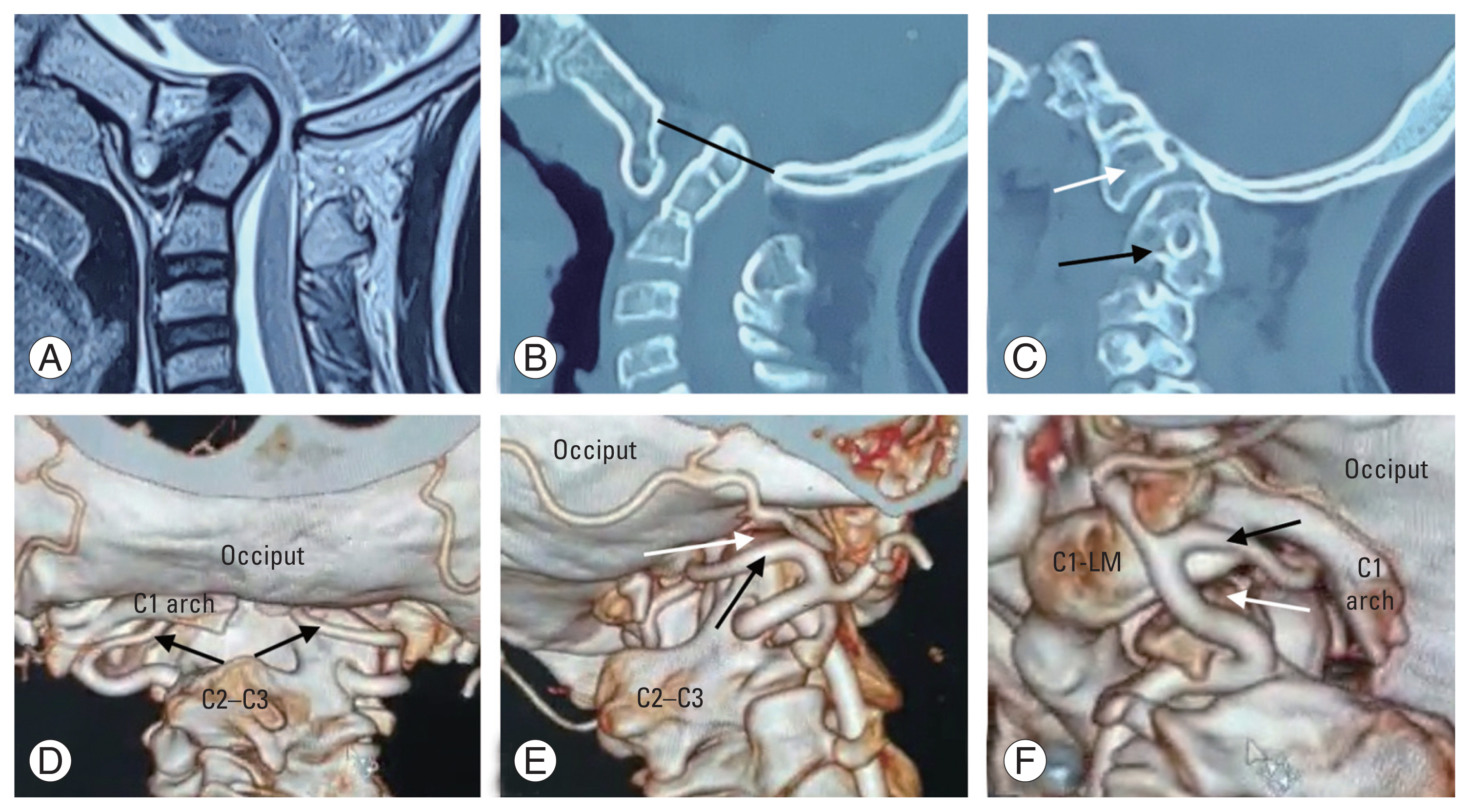
Preoperative images of case 1, a 16-year-old male. (A) Preoperative magnetic resonance imaging of the craniovertebral junction (CVJ) shows cord compression with myelomalacia changes. (B) Computed tomography (CT) scan of the mid-sagittal section of CVJ showing atlantoaxial dislocation with significant basilar invagination (McRae line in black). (C) Para-sagittal CT image of right C1–C2 joint space with overhanging superior facet of C2 along with low-lying occiput obscuring the joint space with fused C2–C3 vertebra (black arrow) and assimilated C1 (white arrow). (D) CT angiography of the neck vessels with three-dimensional reconstruction shows bilateral fenestrated vertebral artery (VA) coursing posterior to the C1–C2 joints space on both sides (black arrows), (E) lateral view of the right C1–C2 joint space with overhanging C2 superior facet (white arrow) and traversing fenestrated VA (black arrow), and (F) lateral view of the left C1–C2 joint space with overhanging C2 superior facet (white arrow) and traversing fenestrated VA (black arrow). C1-LM, C1 lateral mass; C2–C3, C2–C3 fused spinous process.
As a result of bilateral deep-seated C1 LM and VA running across the C1–C2 joints, C1–C2 joint exploration by standard subperiosteal dissection appeared difficult; thus, bilateral C2 superior facet osteotomy was performed (Fig. 3A–C). After drilling the whole depth of the superior facets, the lower part of the C1–C2 joint was exposed and prepared for fusion without VA mobilization or C2 nerve root sacrifice (Fig. 3D). C1-LM reduction screws were placed in standard fashion. C2 subfacetal screws were placed and connected with C1 screws, and reduction was achieved. An autologous bone graft was used for fusion combined with foramen magnum decompression. Postoperative images showed the reduction of AAD and BI (Fig. 3E, F). The neurological condition immediately improved following surgery, and on postoperative day 5, the patient was discharged. No complications were observed at the 3-month follow-up.

(A) Schematic diagram of Fig. 2E showing right C1–C2 joint space of case 1 (C1 in orange and fused C2–C3 in green) with area marked for C2 subfacetal osteotomy (black arrow). (B) After osteotomy (black arrow), showing now exposed inferior facet of C1-LM (white arrow). (C) Intraoperative image showing drilling of the superior facet of C2 (white arrow) with Penfield dissector retracting the fenestrated vertebral artery superiorly (white arrowhead). (D) Exposed inferior facet of C1-LM (white arrow). (E) Mid-sagittal section of postoperative computed tomography (CT) scan showing reduction of atlantoaxial dislocation and basilar invagination (McRae line in black). (F) Postoperative CT scan of para-sagittal images through right C1–C2 joint space showing C1-LM screw placement with C2 superior subfacetal osteotomy. C1-LM, C1 lateral mass; C2–C3, C2–C3 fused spinous process.
2) Case 2
A 36-year-old man complained of weakness in all four limbs and limited neck motions for 1 year. During neurological evaluation, his MRC grade indicated spastic quadriparesis (MRC grade 4/5 in all four limbs). Bisk deep tendon reflexes were noted on all major joints. Extensor plantar reflexes and positive Hoffmann sign were noted bilaterally. Bladder and bowel involvement was observed. His breath-holding period was 25 seconds, and sensory modalities were not compromised. On admission, his mJOA score was 13/18.
MRI of the CVJ showed compression at the CVJ region, which correlated with the clinical complaints and neurological examination (Fig. 4A). CT of the midsagittal section of the CVJ revealed BI with AAD (Fig. 4B). The parasagittal CT section through the left C1–C2 facet joint showed almost a vertical joint with C1-LM placed deep and covered by an overhanging C2 superior facet posteriorly (Fig. 4C). The left extradural posterior inferior cerebellar artery (PICA) can be seen running posterior to the left C1–C2 joint on CT angiography of the neck vessels with 3D reconstruction (Fig. 4D, E).
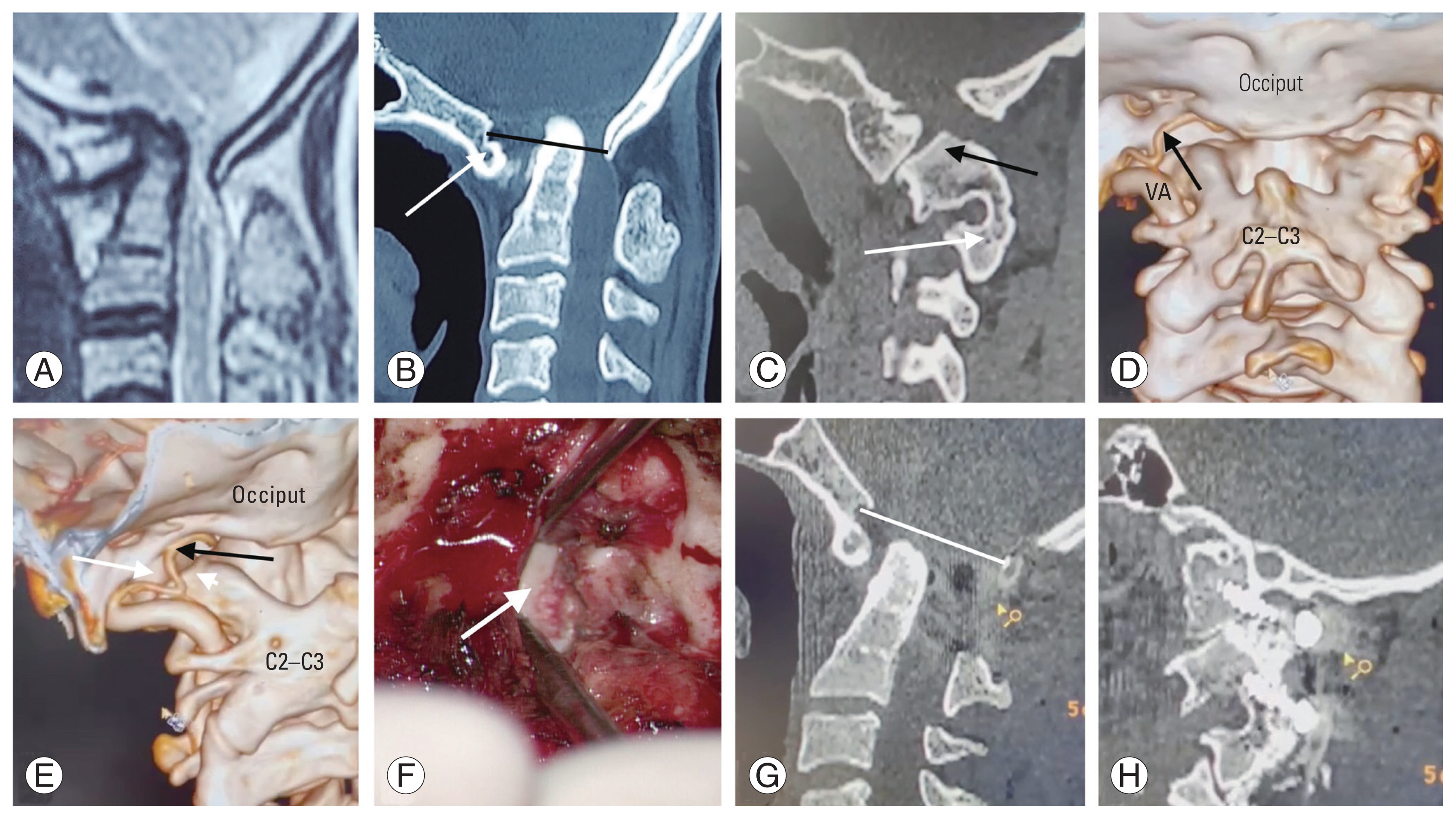
Preoperative images of case 2, a 36-year-old female. (A) Preoperative magnetic resonance imaging of the craniovertebral junction (CVJ) showing cord compression. (B) Computed tomography (CT) scan of the mid-sagittal section of CVJ showing atlantoaxial dislocation with basilar invagination (McRae line in black) with assimilated C1 (white arrow). (C) Para-sagittal CT image of left C1–C2 joint space with overhanging superior facet of C2 (black arrow) along with fused C2–C3 vertebra (white arrow). (D) CT angiography of the neck vessels with three-dimensional reconstruction shows the left extradural posterior inferior cerebellar artery (PICA) (black arrow) coursing posterior to the left C1–C2 joint. The right vertebral artery (VA) is hypoplastic. (E) Lateral view of the left C1–C2 joint space with overhanging C2 superior facet (white arrowhead) and traversing extradural PICA (black arrow) with C1-lateral mass (white arrow). (F) Intraoperative image showing an exposed inferior facet of C1 lateral mass after C2 superior subfacetal osteotomy (white arrow). (G) Mid-sagittal section of postoperative CT scan showing reduction of atlantoaxial dislocation and basilar invagination (McRae line in white). (H) Postoperative CT scan of para-sagittal images through left C1–C2 joint space showing C1 lateral mass screw placement with C2 superior subfacetal osteotomy. C1-LM, C1 lateral mass; C2–C3, C2–C3 fused spinous process.
As the left PICA was endangered, left C2 superior facet osteotomy was performed, and the joint was exposed without the need for soft tissue dissection and PICA mobilization. The lower half of the C1 LM was exposed for the placement of the C1-LM reduction screw (Fig. 4F) on the left side. Right-side joint dissection was performed in a standard subperiosteal manner. Bilateral C1-LM and C2 transpedicular screws were used for fusion combined with foramen magnum decompression. Postoperative images showed the reduction in AAD and BI (Fig. 4G, H). After surgery, immediate postoperative improvement was observed, and the patient was discharged on postoperative day 7. On follow-up at 3 months, he was able to perform routine activities without any support.
Discussion
With the atlantoaxial screw fixation method, the screw is inserted in the most robust region of the spine and at the pivot point of spinal motions [3]. Goel and Laheri [5] introduced the C1-LM screw for AAD in 1994. In normal anatomy, the C1 LM is large enough to safely accommodate a screw with a diameter of 3.5–4.0 mm [6]. Although many C2 fixation techniques have been described in the literature [1], many anatomical and clinical studies have established the superiority of C1-LM screws for C1 fixation [7]. According to Hurlbert et al. [8], only constructs with screw fixation of C1 in addition to C2 exhibited increased stiffness in flexion–extension when compared with normal motion segments.
Doherty and Heggeness [9] discovered that the thickest and most dense cortical bone was located in the anterior cortex of the anterior arch when inserting C1-LM screws, suggesting that the strongest screw should be placed bicortically. Harms and Melcher [10] concurred with this; however, screws that penetrate the anterior C1-LM cortex pose a risk to neurovascular structures [11]. In case 1, the right C1-LM screw had a purchase of two cortical surfaces, which provided good pullout strength as observed intraoperatively despite the short length of cancellous bone purchase.
These are true in normal C1-LM anatomy; however, in complex CVJ cases where C1 is assimilated, the C1 LM and condyles are hypoplastic and fuse to each other, and the morphology and volume of the C1 LM are significantly altered along with an overhanging occiput over the C1–C2 joint [12], making C1-LM screw placement very difficult. In these circumstances, OCF appears to be a viable option. However, OCF should not be preferred, and every attempt should be made to place crews in the C1 LM to prevent subsequent complications, particularly when previous suboccipital craniectomy and C1 laminectomy for Chiari malformations restrict OCF [13]. Furthermore, screw purchase is substantially greater in the atlas thick and massive lateral mass than in the comparatively thin occipital squama [13].
In assimilated C1, the posterior margin of the C1 LM becomes small and disappears in many cases; therefore, the screw entry point must be shifted to the posterior half of the inferior facet of the C1 LM [6,12]. In these cases, C2 is also situated more posteriorly over the C1 LM, obstructing appropriate exposure of the inferior facet of the C1 LM. In these cases, screw insertion at the inferior facet of C1 is challenging. C2 superior facet osteotomy eliminates the obstructive C2 facet and allows for direct entry into the C1 LM via the lower part of the inferior facet of the atlas.
The trajectory of the C1-LM screw also obtains a sharp angulation superiorly because of the overhanging occiput. Excessive superior angulation of C1-LM screws causes the screw head to be extremely close to that of the C2 pedicle screw, making rod insertion between the two screws challenging. The use of reduction screws in the C1 LM alleviates the difficulty in rod insertion [14].
The hypoglossal canal is normally positioned at the top section of the C1 LM and runs parallel to the inferior facet of the C1 LM. Accordingly, when the screw is positioned too superiorly and deeply, the incidence of hypoglossal nerve damage increases [15]. C2 superior facet osteotomy gives an entrance site somewhat inferior to the short posterior border of the assimilated C1 LM, allowing a straight course of screw toward the anterior tubercle of C1 and hence the risk of hypoglossal nerve injury.
An aberrant VA course is prevalent in complicated CVJ cases [16]. According to Hong et al. [16], 4.7% of the VAs run beneath the C1 posterior arch and 0.6% run as fenestrated arteries, as was in our case where bilateral VAs were fenestrated and placed posterior to the C1–C2 facet joint. Similarly, Tokuda et al. [17] showed that the VAs ran beneath the C1 posterior arch in 0.7% of patients without bone anomalies; however, this increased to 19.1% in patients with C1 assimilation and Klippel-Feil disease. In addition, the PICA can emerge from the extracranial section of the VA and even between C1 and C2 [18]. In these individuals, exposure and opening of the C1–C2 facet joint are dangerous; thus, C1-LM screw placement is extremely difficult. After the drilling of the C2 superior facet, the C1–C2 joint is exposed in the inferior part, enabling easy placement of the C1-LM screw, without dissecting or mobilizing the aberrant vasculature crossing the C1–C2 facet joint.
The C2 ganglion is located on the posterior side of the C1–C2 joint. It is a significant limiting factor that prevents effective visualization of the C1–C2 facet joint. In addition, it might be bulky, with a vast perineural venous plexus. It restricts exposure and proper drilling at the C1–C2 joint, which might discourage intraoperative manipulation and bone fusion. Moreover, the abnormal VA course in complicated AAD necessitates root sectioning because the VA is positioned ventral to it [19]. Thus, sacrificing the C2 ganglion is preferred to effectively visualize the C1 facet and place C1-LM screws under direct vision [20]. The technique also reduces operating time and blood loss by avoiding dissection of the periganglionic venous plexus [21].
Although cutting the C2 nerve root is tempting, certain drawbacks are proposed. C2 nerve sacrifice may result in postoperative numbness or dysesthesia across the occiput and retroauricular region [21]. Elliott et al. [21] discovered occipital numbness in 12% of their patients. This hypoesthesia in the C2 dermatome might aggravate ulcer development. After the removal of the C2 superior facet, sectioning of the C2 nerve root is no longer required, as the root will be superior to the C1–C2 joint exposure and C1–LM entry point. Thus, C2 superior facet removal enables C1-LM screw placement in complex CVJ anomalies without risk of VA injury or complications of C2 nerve root sectioning.
In conclusion, C2 superior facetal osteotomy is a novel screw placement technique for the treatment of complex CVJ abnormalities. Even when C1-LM screw placement is challenging, this approach allows the exposure of the C1–C2 joint without risk of neurovascular injury and can promote rigid and robust C1–C2 fusion. The need for OCF in complex CVJ cases is minimized, with a lower chance of C2 nerve sectioning and VA damage. C2 superior facet removal is a technically easy technique and allows C1-LM screw placement with ease in most cases.
Notes
Conflict of Interest
No potential conflict of interest relevant to this article was reported.
Author Contributions
All authors contributed equally to the conception or design of the work, acquisition, analysis, interpretation of data for the work, drafting the work or revising it critically for important intellectual content.