Role of the O-arm and Computer-assisted Navigation of Safe Screw Fixation in Children with Traumatic Rotatory Atlantoaxial Subluxation
Article information
Abstract
Study Design
A retrospective analysis of 7 patients with traumatic rotatory atlanto-axial subluxation.
Overview of Literature
Cases of traumatic rotatory atlantoaxial subluxation in children are difficult to be stabilized. Surgical challenges include: narrow pedicles, medial vertebral arteries, vertebral artery anomalies, fractured pedicles or lateral masses, and fixed subluxation. The use of O-arm and computer-assisted navigation are still tested as aiding tools in such operative modalities.
Purpose
Report of clinical series for evaluation of the safety of use of the O-arm and computed assisted-navigation in screw fixation in children with traumatic rotatory atlantoaxial subluxation.
Methods
In the present study, 7 cases of rotatory atlantoaxial traumatic subluxation were operated between December 2009 and March 2011. All patient-cases had undergone open reduction and instrumentation using atlas lateral mass and axis pedicle screws with intraoperative O-arm with computer-assisted navigation.
Results
All hardware was safely placed in the planned trajectories in all the 7 cases. Intraoperative O-arm and computer assisted-navigation were useful in securing neural and vascular tissues safety with tough-bony purchases of the hardware from the first and only trial of application with sufficient reduction of the subluxation.
Conclusions
Successful surgery is possible with using the intraoperative O-arm and computer-assisted navigation in safe and proper placement of difficult atlas lateral mass and axis pedicle screws for rotatory atlantoaxial subluxation in children.
Introduction
The C1-C2 joint is the most active joint in the body, reported to move at least 600 times an hour. The facet orientation at this joint allows excellent rotation at the expense of bony stability, especially in children. Rotatory atlantoaxial subluxation is an uncommon, poorly understood condition that occurs primarily in children [1,2].
Variable wiring techniques have been described in the surgical treatment of C1-C2 subluxation [3-5]. Fluoroscopically-controlled bilateral insertion of trans-articular screws, and polyaxial-head screws in the lateral mass of C1 and into the pedicle of C2 were described by other researchers as a mode of treating this pathology [6,7].
Complications of screw placement in spinal instrumentation can be serious and include vascular, visceral, and/or neurological injury [8]. Different tools are now in use to increase the safety and accuracy of screw insertion in spinal instrumentation procedures. The computer-assisted image guidance system was originally designed primarily to support orthopedic surgery. Its clinical applications in spine surgery show that the three-dimensional (3D) computed tomography (CT) scan acquisition mode provides superior imaging information in pedicle screw position, compared to conventional radiographs or fluoroscopy alone [9]. In addition, the computer-assisted technique has a potential for image-guide screw placement [10].
After image-guided spinal surgery was introduced to increase the accuracy of spinal instrumentation placement, the computer-assisted image guidance systems allow for the safer and more accurate placement of pedicle screw-rod constructs with a significant reduction in exposure to ionizing radiation to the operating surgeon [11,12].
The purpose of the present study is to evaluate the safety and accuracy of using the O-arm and computed assisted-navigation in screw fixation in children with traumatic rotatory atlantoaxial subluxation.
Materials and Methods
We present a retrospective analysis of 7 patients with traumatic rotatory atlanto-axial subluxation. The study was reviewed and approved by the Institutional Review Board. The patients ranged in age from 5 and 14 years old; 4 patients have Down syndrome. All patient-cases underwent an operation in our institute between December 2009 and March 2011. All patients were subjected to instrumentation by atlas lateral mass screws and axis pedicle screws, atlanto-axial open reduction, correction of deformity, then bone allograft fusion.
Preoperative planning was carried out to get a detailed idea on the measurements and preliminary trajectories of the screws; the position of vertebral arteries and the neural structures by studying the preoperative CT, computed tomography angiography (CTA), and magnetic resonance imaging (MRI) of the cervical spine.
In all cases, the O-arm and computer-assisted navigation system (O-arm Surgical Imaging System and StealthStation S7, Medtronic, Minneapolis, MN , USA) were used.
Each patient's head was held in the Mayfield head-rest system in the torticollis prone position, the O-arm is then used to take fluoroscopy image in antero-posterior and lateral views to assure that the C1 and C2 vertebrae are in the center of the O-arm gantry. Then, the reference frame was attached to an extension of the Mayfield head rest system.
After preparation and draping of the surgical field, the midline posterior nuchal skin incision was made and subperiosteal muscle dissection was achieved. Great care was taken while dissecting around the vertebral arteries especially where they are stretched or having abnormal course. The exact course of the vertebral arteries was confirmed by the intraoperative micro-Doppler in every case.
The sterile draped O-arm is used to take a 3D CT with medium dose of irradiation on the setting up to reduce the dose of exposure to the patient. With the advent of intraoperative imaging coupled to navigation systems the registration time is no longer a problem. While the imaging is acquired intraoperatively, when the O-arm is coupled to the navigation system, the registration process is automated and a user dependent manual registration is no more required. This saves a voluble time and improves accuracy of Navigation. The images acquired are rapidly transferred to the navigation workstation, where multi-planar reconstructions of the anatomy are generated. At this stage the Navigation is ready and the surgery can continue. The time required for a scan, using the O-arm, is 13 seconds (25 seconds for a high resolution scan). The transfer of the scan from the O-arm, through the Mobile View Station, to the navigation is taking less than a minute. Consequently, it is taking less than 2 minutes; from the moment the scan is started until the navigation is ready and the surgery can be resumed.
Polyaxial-head titanium screws were inserted in atlas lateral mass and axis pedicle with the guidance of intraoperative computer-assisted navigation (Fig. 1). After proper decompression, the atlantoaxial rotatory subluxation was manually corrected by loosening the joints of the Mayfield head rest system. The open reduction was carried out under microscopic visual control by the surgeon, with monitoring of neurophysiology and anesthesia. After the proper reduction, the head clamp was reattached to the swivel adapter and all of its joints were secured. Then, the integrity of the vertebral arteries was confirmed by the intraoperative micro-Doppler flow meter.

Intraoperative image of 3D-computer-assisted navigation shows the proper entry point; trajectory and measurements of the right C1 lateral mass screw.
Then, the final head position, screws trajectories, and relationship between atlas and axis facets were checked by 2D fluoroscopy and 3D CT using the O-arm. After final confirmation of satisfactory reduction and hardware placement, the 2 screws on each side were connected with rods; then the bone graft was laid on.
Postoperatively, the 4 patients with Down syndrome were kept in Halo vests, as they have lax ligaments with a lower fusion rate that needed external immobilization to achieve better fusion. The other cases were kept in a rigid cervical collar for 1.5 months. Postoperative CT cervical spine was used to evaluate the safety and accuracy of the inserted screws to the preoperative planned trajectories. Follow-up visits were scheduled for each case at 3, 6, and 12 months postoperatively.
Results
The characteristic features of the studied cases are presented in Table 1. The availability of intraoperative 3D CT cuts to confirm the proper screw placement, while the patient was still anesthetized helped us to avoid additional surgery for screw readjustment (Fig. 2).

The characteristic features of the studied cases

Intraoperative reformatted computed tomography image using O-arm shows proper screw insertion into the left C2 pedicle.
In this series, there was no incidence of dural laceration, screw application failure, vertebral artery injury, or other intraoperative complication. Postoperative CT cervical spine showed accurate and safe screw insertion, as in the preoperative planned trajectories without vascular or neural encroachment (Figs. 3, 4). The subluxation was reduced satisfactorily and the deformity disappeared. Postoperatively, case 4 showed right occipital neuralgia that improved 4 months postoperatively; this may have been due to irritation of the C2 ganglion by the pedicle screw on that side.
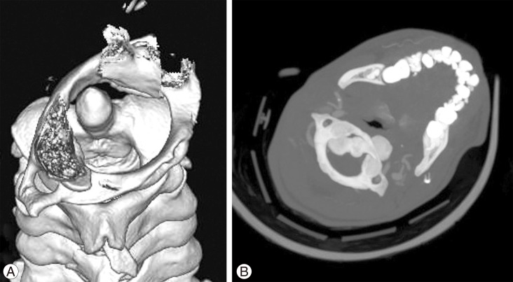
(A) Preoperative 3D reformatting computed tomography (CT) image shows bilateral subluxation of C1-C2 facet joints; the Odontoid is occupying the anterior 1/3 of the cervical canal that is still capacious enough for the cord; this may explain that the patient is neurologically intact. (B) Preoperative CT bone window axial view at the level of C1-C2 shows the C1-C2 rotatory subluxation.
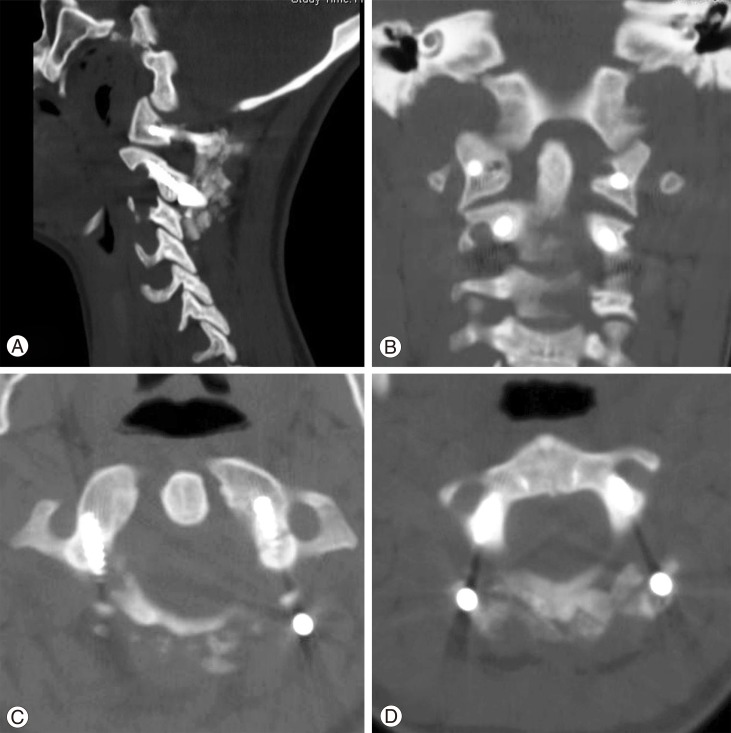
(A) Postoperative computed tomography (CT) bone window, sagittal view image shows the proper screw placement of the C1 lateral mass and C2 pedicle screws. (B) Postoperative CT bone window, coronal view image shows the screw placement of the C1 lateral mass and C2 pedicle screws and restoration of C1-C2 facet joints alignment. (C) Postoperative CT bone window, axial view image at the level of C1 ring shows the proper trajectory of both C1 lateral mass screws and its relationship to the vertebral artery foramina bilaterally. Note, the on-lay bone graft lies on the back of the C1 posterior arch and screw sites. (D) Postoperative CT bone window, axial view image at the level of C2 shows the decent trajectory of both C2 pedicles screws and its relation to the vertebral artery foramina bilaterally.
In the follow-up period, starting bone graft fusion and acceptable correction of the preoperative subluxation were demonstrated with no incidence of implant failure (Fig. 5).
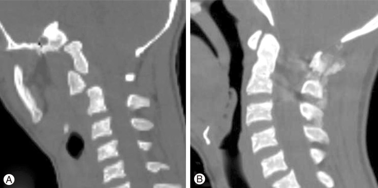
(A) Preoperative computed tomography (CT) bone window sagittal view at the level of C1-C2 shows the C1-C2 rotatory subluxation and displacement. The cuts through the skull and C1 are in different plane than those through C2 and subaxial spine, a position imposed by torticollis. (B) Postoperative CT bone window sagittal view at the level of C1-C2 in the mid-sagittal view shows the restored alignment between C1 and C2.
Discussion
In children, the atlantoaxial joints are horizontal and shallow, the ligaments and joint capsules have sufficient elasticity to allow increased mobility without disruption. The disproportion between the size of the head and neck and the poorly developed neck musculature may dispose these joints to excessive forces and endanger their stability [13].
The Committee on Sports Medicine of the American Academy of Pediatrics has recommended that C1-C2 arthrodesis should be considered only in patients with C1-C2 subluxation or dislocation with neurological signs or symptoms [14]. Gallie's strategy favored operative stabilization even without neurologic signs at presentation, as he believed that neurologic compromise will likely develop later if displacement recurs or increases [4]. In our series, we followed Gallie's strategy in decision making, as we felt that to be safer for our patients who presented late after their subluxation occurrence.
The posterior wire stabilization of C1-C2 instability does not provide sufficient immobilization, with nonunion rates up to 30% even with adjunctive halo vest immobilization. Cable insertion beneath the lamina exposes the patient to the risk of spinal cord injury [6].
On the other hand, approximately 20% of patients requiring atlantoaxial fusion show anatomic variations in the path of vertebral artery and in the osseous anatomy, at least on one side, precluding lateral mass or pedicle screw placement that makes our decision to apply these screws even more challenging [6].
The technique of placement of C1 lateral mass and C2 pedicle screws coupled with fluoroscopically controlled open reduction maneuver avoids damage to the C1-C2 facet joint and thus can be used in patients who require an open reduction followed by limited fixation [6].
Fielding believed that the normal anatomical relationship between C1 and C2 should be restored for fusion [15]. We broadly agree with this strategy, yet, in all the included cases we achieved an acceptable reduction.
The O-arm was introduced for image-guided surgery applications where the location of a structure is emphasized over a survey of all image details. For this specific application, the O-arm has some advantages over a CT scan due to its wide coverage, lower radiation exposure, and acceptable image quality [10].
Linhardt et al. [16] demonstrated increased pullout strength in pedicle screws placed with computer-assisted techniques compared with screws placed with conventional techniques. Nottmeier et al. [17] believe that using the 3D planning function of the image guidance system allows larger diameter screws to be placed and can result in screws being placed in a more medial trajectory than standard techniques. Their study was largely designed on thoraco-lumbar screws. However, our study is more challenging as it was applied on the cervical spine.
In the presented study, Preoperative CT, CTA, and MRI of the cervical spine were helpful for pre-operative planning of the measurements and preliminary trajectories of the screws in relation to the position of vertebral arteries and the neural structures. The image-guided spinal instrumentation coupled with O-arm 3D CT-quality images was of tremendous help in placing proper screws in proper and difficult trajectories. The provision of axial cuts for the instrumented levels was of extreme benefit in deciding the proper screw trajectory and safety of the adjacent neural and vascular structures, and adequacy of reduction by studying the restored relation between the previously misaligned facets, while the patient is still on the operating table.
Ishikawa et al. [18] used the intraoperative O-arm-based navigation system for 801 cervical pedicle screw insertions in 21 patients and the cervical pedicle screw positions were classified according to pedicle-wall perforations, by using postoperative CT. Ninety-six screws (88.9%) showed no perforation in his series. In our present study, the C1 lateral mass and C2 pedicle screw insertion were more challenging, because of the rotatory subluxation that led to anatomical distortion of the nearby neurovascular structures. Using of the intraoperative O-arm-based navigation system resulted in accurate screws insertion as in the preoperative planned trajectories without vascular or neural encroachment.
Since the O-arm introduction, questions concerning patient dose and risks to operators from scattered radiation, especially during its 3D scan acquisition mode, have been raised. The radiation exposure by the O-arm concerns the researchers in two fields; patient exposure and operating room team exposure. Also, comparison is carried out between the O-arm and both ordinary fluoroscopy and multi-slice CT. Comparison is difficult as the condition in question is multi-factorial [19]. We agree about this notion and carrying out a joint study with radiology department in our institute to investigate this issue.
The manual registration process is time consuming and its accuracy is user-dependent. With the advent of intraoperative imaging coupled to navigation systems, the registration time is no longer a problem. The automated registration process minimizes the inherent limitations associated with manual registration. Furthermore, since the imaging is obtained after the patient is positioned on the operative table, the difference in inter-segmental relationship, between the patient position during the scan and surgical position on the operative room (OR) table, as seen with preoperative CT-based navigation, is eliminated. This eradicates the need to repeat the registration for every single vertebra of the surgical segment.
Finally, intraoperative imaging allows for the assessment of the surgeon's objectives, within the OR itself, while the patient is anesthetized and on the surgical table, and before closing the surgical incision.
Conclusions
Successful surgery is possible with use of the intraoperative O-arm and computer-assisted navigation in safe and proper placement of difficult atlas lateral mass and axis pedicle screws for rotatory atlantoaxial subluxation in children.